Phase-change metal thermal interface composite material and preparation method thereof

A technology of phase-change metals and composite materials, applied in heat exchange materials, metal layered products, chemical instruments and methods, etc., can solve problems such as short circuits, voids, and phase separation

Active Publication Date: 2014-06-18
SHENZHEN INST OF ADVANCED TECH CHINESE ACAD OF SCI
View PDF4 Cites 14 Cited by
  • Summary
  • Abstract
  • Description
  • Claims
  • Application Information

AI Technical Summary

Problems solved by technology

However, a larger snap-fit ​​force is required to achieve a thinner thickness to achieve low thermal resistance, and problems of overflow and phase separation are prone to occur during use
Although the thermal conductive adhesive will not overflow, it needs to be cured at high temperature during use.
Although the traditional polymer-based thermal phase change materials combine the advantages of thermal grease and thermal pads, the thermal conductivity and thermal resistance still cannot meet the requirements of some occasions that require high heat dissipation.
Although metal solder can have extremely low thermal resistance and high heat dissipation capacity, ordinary solder is used as a thermal interface material, and it is not as convenient to use and install as thermal pads or thermal phase change materials in many occasions.
[0004] Phase-change metal thermal interface materials are currently a hot topic in the research of thermal interface materials, but there are still various problems in the existing phase-change metal thermal interface materials. Deformation fills the interface gap, excessive pressure will not only generate unfavorable stress and cause damage to electronic devices, but also easily cause overflow of molten phase-change metals, resulting in voids and short circuits
Aiming at the phenomenon of molten phase-change metal overflowing, at present, the ring gasket is mainly installed on the alloy outer ring, but this method is prone to failure after a period of working time, and it is difficult to achieve the effect of leak prevention

Method used


Image

  • Phase-change metal thermal interface composite material and preparation method thereof
  • Phase-change metal thermal interface composite material and preparation method thereof
  • Phase-change metal thermal interface composite material and preparation method thereof

Examples


preparation example Construction

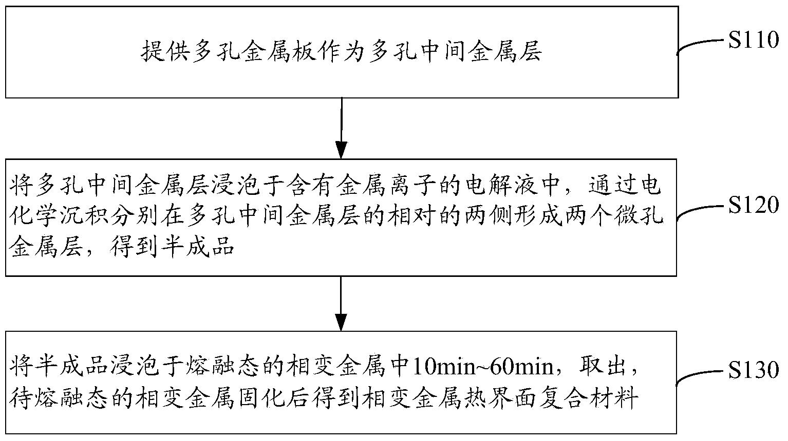
[0038] see figure 2 , a method for preparing a phase-change metal thermal interface composite material in an embodiment includes the following steps S110 to S130.

[0039] Step S110: providing a porous metal plate as a porous intermediate metal layer.

[0040] The porous intermediate metal layer is preferably a porous copper foam layer, a porous nickel foam layer, a porous aluminum foam layer or a porous silver foam layer.

[0041] Preferably, the thickness of the porous intermediate metal layer is 0.005mm-0.5mm. The porosity of the porous intermediate metal layer is 30% to 90%, preferably 60%.

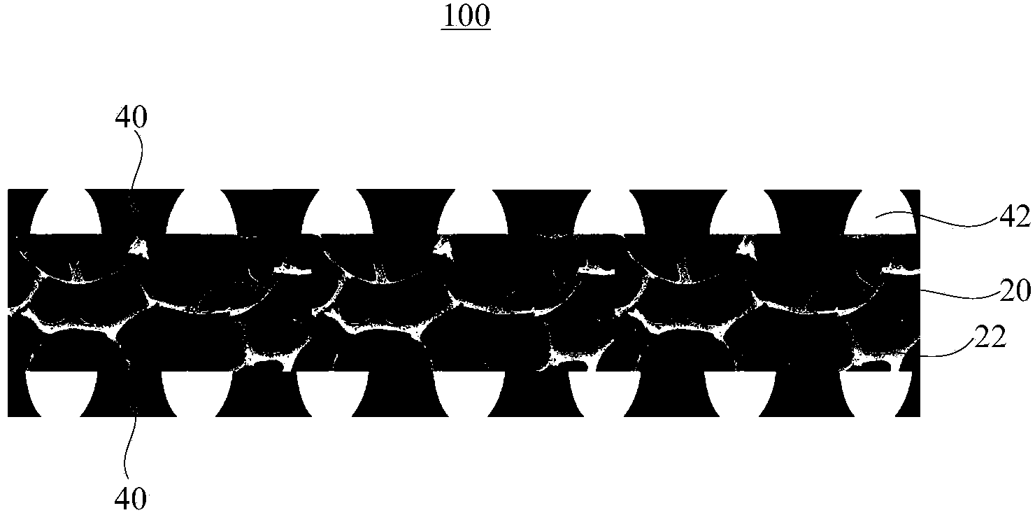
[0042] Step S120: Soak the porous intermediate metal layer in an electrolyte solution containing metal ions, and form two microporous metal layers on opposite sides of the porous intermediate metal layer by electrochemical deposition to obtain a semi-finished product.

[0043]Electrolytes containing metal ions include sulfuric acid and metal ions. The metal ion is a metal ion cor...

Embodiment 1

[0057] Preparation of phase change metal thermal interface composites

[0058] 1. Provide a commercial porous foamed copper foil with a thickness of 0.068m and a porosity of 60% as the porous intermediate metal layer. The length × width of the porous intermediate metal layer is 25mm × 25mm;

[0059] 2. Soak the porous intermediate metal layer in an electrolyte solution containing 0.2M CuSO 4 and 1.0M of H 2 SO 4 , with a current of 9.42A, after electroplating for 30S, two microporous metal layers are formed on the opposite two sides of the porous intermediate metal layer to obtain a semi-finished product; the thickness of each microporous metal layer is 0.001mm, and each micropore There are multiple micropores on the metal layer, the diameter of the micropores is 30 μm, and the distance between two adjacent micropores is 30 μm to 50 μm;

[0060] 3. Mix 3.16g of metal bismuth with a purity greater than 99.9%, 1.96g of metal tin with a purity greater than 99.9%, and 4.88g of ...

Embodiment 2

[0068] Preparation of phase change metal thermal interface composites

[0069] 1. Provide a commercial porous nickel foam foil with a thickness of 0.024m and a porosity of 60% as the porous intermediate metal layer. The length × width of the porous intermediate metal layer is 25mm × 25mm;

[0070] 2. Soak the porous intermediate metal layer in the electrolyte, which contains 0.2M AlCl 3 and 1.0M of H 2 SO 4 , with a current of 15A, and after electroplating for 10S, two microporous metal layers are formed on the opposite two sides of the porous intermediate metal layer to obtain a semi-finished product; the thickness of each microporous metal layer is 0.0005mm, and each microporous metal layer There are multiple micropores on the layer, the diameter of the micropores is 50 μm, and the distance between two adjacent micropores is 40 μm to 50 μm;

[0071] 3. Mix 3.4g of metal bismuth with a purity greater than 99.9%, 1g of metal gallium with a purity greater than 99.9%, and 5.6...


PUM

PropertyMeasurementUnit
thicknessaaaaaaaaaa
pore sizeaaaaaaaaaa
thicknessaaaaaaaaaa

Abstract

The invention relates to a phase-change metal thermal interface composite material and a preparation method thereof. The phase-change metal thermal interface composite material comprises a porous middle metal layer, two microporous metal layers respectively arranged at two opposite sides of the porous metal layer, and phase-change metal, wherein the the porous middle metal layer and the two microporous metal layers are filled with the phase-change metal. The composite material has the advantages that the porous middle metal layer serving as a structure supporting layer can bear certain pressure to ensure that the phase-change metal in a molten state cannot be extruded and overflown and the phase-change metal can run through up and down to ensure that the phase-change metal thermal interface composite material has the low thermal resistance and the high heat-conducting property; the phase-change metal can be effectively prevented from being overflown by adopting the two microporous metal layers, after being molten and expanded, the phase-change metal can be oozed from micropores of the microporous metal layers to effectively fill up gaps in the composite material and no hole occurs in the using process.

Description

technical field [0001] The invention relates to the technical field of thermal interface materials, in particular to a phase-change metal thermal interface composite material and a preparation method thereof. Background technique [0002] At present, electronic devices are gradually developing towards miniaturization and high integration. As the operating speed becomes faster and faster, the heat generated by the heating electronic components also increases, and the rise in temperature directly leads to the shortening of the service life of electronic devices. Therefore, it is particularly important to develop thermal interface materials with high thermal conductivity and low thermal resistance. [0003] At present, thermal interface materials on the market are mainly divided into thermal grease, thermal adhesive, thermal pad, thermal phase change material, metal solder and so on. The thermal resistance of thermal grease is between 0.2~0.6*℃cm 2 / W, easy to use. However,...

Claims


Application Information

Patent Timeline
Patent Type & Authority Applications(China)
IPC IPC(8): B32B15/01B32B3/24H01L23/427C09K5/06C25D7/00
Inventor 孙蓉任虎鸣符显珠郭慧子
Owner SHENZHEN INST OF ADVANCED TECH CHINESE ACAD OF SCI
Why Eureka
Try Eureka