Discharge-amount limiting tool for pumping liquid container

A liquid container and discharge volume technology, applied in liquid distribution, household utensils, brackets or dispensers, etc., can solve problems such as waste, environmental pollution, liquid waste, etc., and achieve the effect of easy removal and operation

Inactive Publication Date: 2004-04-14
PIONEER CORP +1
View PDF3 Cites 7 Cited by
  • Summary
  • Abstract
  • Description
  • Claims
  • Application Information

AI Technical Summary

Problems solved by technology

[0008] In order to solve the above-mentioned problems, the purpose of the present invention is to limit the amount of pushing in when the suction pipe of the pump type liquid container is pushed in without adjusting the amount of pushing in, so as to limit the discharge amount produced by one push-in action. Therefore, it is possible to eliminate the unsuitable situation that it

Method used


Image

  • Discharge-amount limiting tool for pumping liquid container
  • Discharge-amount limiting tool for pumping liquid container
  • Discharge-amount limiting tool for pumping liquid container

Examples


Example Embodiment

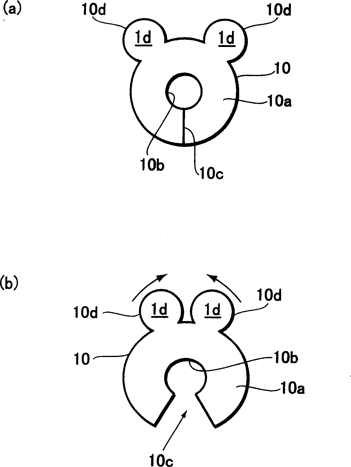
[0062] Figure 11 (a) is an explanatory diagram of the dimensional relationship between the pump-type liquid container and the discharge amount limiter attached to the pump-type liquid container in the embodiment of the present invention.

[0063] Regarding the width L1 of the main body member 10 in the discharge amount limiter 1, since the lower surface of the nozzle A3 must be brought into contact with the receiving portion 10a to stop the pressing-in of the suction pipe A2, it must be wider than the nozzle A3 W is bigger. In addition, the diameter L2 of the mounting hole 10b in the main body member 10 is generally larger than the outer diameter of the threaded portion A4 formed in the suction pipe A2.

[0064] The nozzle A3 is usually made of plastic, such as Figure 11 As shown in (b), the suction pipe A2 and the nozzle A3 are connected by a plurality of ribs A5. Figure 11 (b) is a perspective view of the suction pipe A2 and the nozzle A3 as viewed from below. In this...


PUM


Abstract

The tool to be mounted on a suction tube A2 on a pump-type liquid container A limits the pushed-in amount of the tube A2. Its body member 10 consists of an elastically deformable single member, and has a receive 10a for receiving the lower surface of a nozzle A3 when the nozzle is pushed in, a mounting hole 10b into which the suction tube A2 is fitted, a closed cut 10c extending from the outer rim of the body member 10 to the hole 10b, and a tab 10d for elastically deforming the member 10 to open the cut 10c.

Description

technical field [0001] The present invention relates to a pump discharge volume limiter for limiting the discharge volume of a pump type liquid container. Background technique [0002] Pump-type liquid containers are widely used for liquid soap, shampoo, detergent and other liquids. This pump-type liquid container has a suction pipe as an operating part of the pumping mechanism equipped in the container. The suction pipe protrudes vertically from the mouth of the container through a cover that airtightly closes the mouth. The head of the nozzle on the upper part of the suction pipe is pressed downward to press the suction pipe, and the liquid in the container is discharged through the suction pipe and the nozzle. [0003] This pump-type liquid container has a structure in which the amount of discharge in one operation is adjusted by the stroke amount of the suction pipe protruding from the cap. However, it is difficult to spit out the required amount with the adjustment of...

Claims


Application Information

Patent Timeline
IPC IPC(8): A47K5/12B65D47/34B65D83/22
CPCB05B11/3008B05B11/1008
Inventor 渡边将义仲川孝幸
Owner PIONEER CORP
Why Eureka
Try Eureka