Projecting apparatus

A projector and projection technology, applied in the field of projectors, can solve problems such as the impossibility of giving the correct position

Inactive Publication Date: 2004-04-14
NEC DISPLAY SOLUTIONS LTD
View PDF3 Cites 39 Cited by
  • Summary
  • Abstract
  • Description
  • Claims
  • Application Information

AI Technical Summary

Problems solved by technology

[0009] Also, also regarding the position to be detected, it is impossible to give the correct position due to installation errors of the rangefinder and variations in the mechanical positional relationship between the projection lens and the display device
[0010] Also, where structures like frames exist outside the screen and protrude beyond the ends, or said screen itself is mounted very far away, etc., the position measured by the rangefinder does not always match the position of the screen

Method used


Image

  • Projecting apparatus
  • Projecting apparatus
  • Projecting apparatus

Examples


no. 1 Embodiment approach

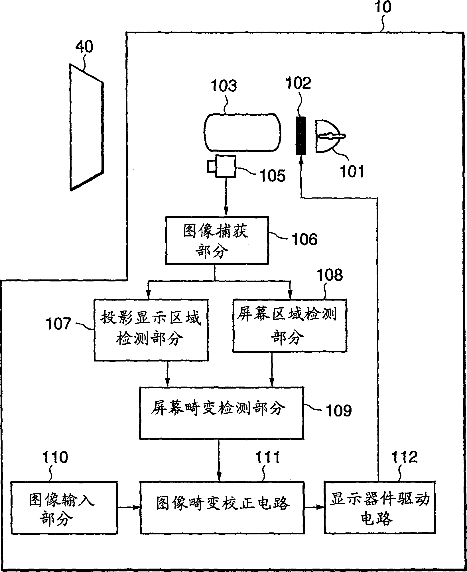
[0043] A first embodiment of the present invention will be described below. figure 1 A block diagram of a first embodiment of the invention is shown. Projector 10 projects and displays an image on screen 40 . The projector 10 includes a light source 101, a display device 102, a projection lens 103, an image sensor 105, an image capture part 106, a projection display area detection part 107, a screen area detection part 108, a screen distortion detection part 109, an image input part 110, An image distortion correction circuit 111, and a display device driving circuit 112.

[0044] The projected image is displayed on the screen 40 through the light source 101 , the display device 102 and the projection lens 103 . A lighting lamp is used as the light source 101 . The display device 102 employs a liquid crystal panel. The image sensor is adjacent to the projection lens 103 and is located so close that its distance is negligible compared to the distance to the screen 40 . The...

no. 2 Embodiment approach

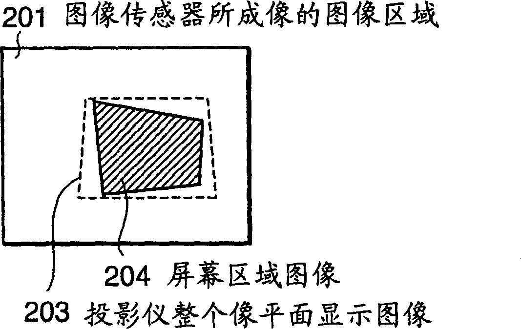
[0069] A second specific embodiment of the present invention will be explained below. In the second specific embodiment, as attached Figure 8 As shown, when the screen area is detected, the screen area image 204 does not enter the display image 203 area of ​​the entire image plane of the projector.

[0070] In this case, the steps of the first embodiment do not allow the user to obtain a satisfactory image. hereby refer to the attached Figure 8 Explain what to do in this situation. The screen area detection section 108 detects the area of ​​the screen 40 in the same method as in the first embodiment. The screen distortion detection section 109 similarly enlarges or reduces the area, and further performs position shifting if necessary. The size and position of the image is calculated such that the image projected onto the screen 40 remains rectangular and within the area of ​​the displayed image 203 of the entire image plane of the projector. By displaying an image at th...

no. 3 Embodiment approach

[0073] A third specific embodiment of the present invention will be explained below. attached Figure 9 It is a block diagram showing the optical system of the third embodiment. Projector 10 has half mirror 113 between display device 102 and projection lens 103 . Half mirror 113 directs the image through projection lens 103 to image sensor 105 . If the half mirror 113 is a mobile system, wherein the half mirror 113 is only placed between the display device 102 and the projection lens 103 when being imaged by the image sensor 105, then in normal use the half mirror 113 will not Affects projector 10.


PUM


Abstract

An image sensor is installed in the vicinity of a projection lens. The image sensor images a projected and displayed image and a screen. A projection display area and a screen area are detected from the image imaged by the image sensor. An inputted image data is corrected so that the projection display area matches the screen area. The image to be displayed is automatically displayed in a shape, which matches a display surface of the screen.

Description

technical field [0001] The present invention relates to a projector for projecting and displaying images on a screen. Background technique [0002] Up to now, correcting keystone distortion due to oblique projection of images by vertical processing is a known method, while in the horizontal direction, the projector is usually installed at a position facing the screen at right angles. [0003] However, with the advent of horizontal keystone correction functions in recent years, it has become possible to achieve vertical, horizontal and diagonal corrections. [0004] In these correction methods, the correction of the screen still relies on manual correction. If it is only to correct vertical or horizontal keystone distortion, it is easy to do it manually, but it is difficult to correct diagonal distortion manually. [0005] There are proposed systems (for example, the inventions disclosed in Japanese Unexamined Patent Application Publication No. 2001-169211 and No. 2001-0839...

Claims


Application Information

Patent Timeline
Patent Type & Authority Applications(China)
IPC IPC(8): H04N5/74H04N9/31H04N17/00
CPCH04N9/3197H04N5/74H04N9/3194H04N9/3185
Inventor 望月和雄青柳寿和森胁大辅
Owner NEC DISPLAY SOLUTIONS LTD
Why Eureka
Try Eureka