Composite working machine tool and working method in composite working machine tool

A composite machining and machine tool technology, applied in metal processing machinery parts, metal processing equipment, lathes, etc., can solve the problems of increased processing costs, complex tools, and difficulty in arbitrarily setting groove width, groove radius, and groove cross-sectional shape.

Inactive Publication Date: 2004-04-28
MORI SEIKI HITECH
View PDF2 Cites 22 Cited by
  • Summary
  • Abstract
  • Description
  • Claims
  • Application Information

AI Technical Summary

Problems solved by technology

[0007] As mentioned above, in order to machine spiral grooves with complicated shapes on workpieces, a dedicated machine tool was previously required, resulting in increased processing costs, and it was difficult to arbitrarily set the groove width, groove radius, groove cross-sectional shape, etc.
In addition, there is a problem that the calculation of the movement path of the tool becomes complicated when machining the groove by combining the rotation angle of the table and the XY axis movement of the tool.

Method used


Image

  • Composite working machine tool and working method in composite working machine tool
  • Composite working machine tool and working method in composite working machine tool
  • Composite working machine tool and working method in composite working machine tool

Examples


Embodiment Construction

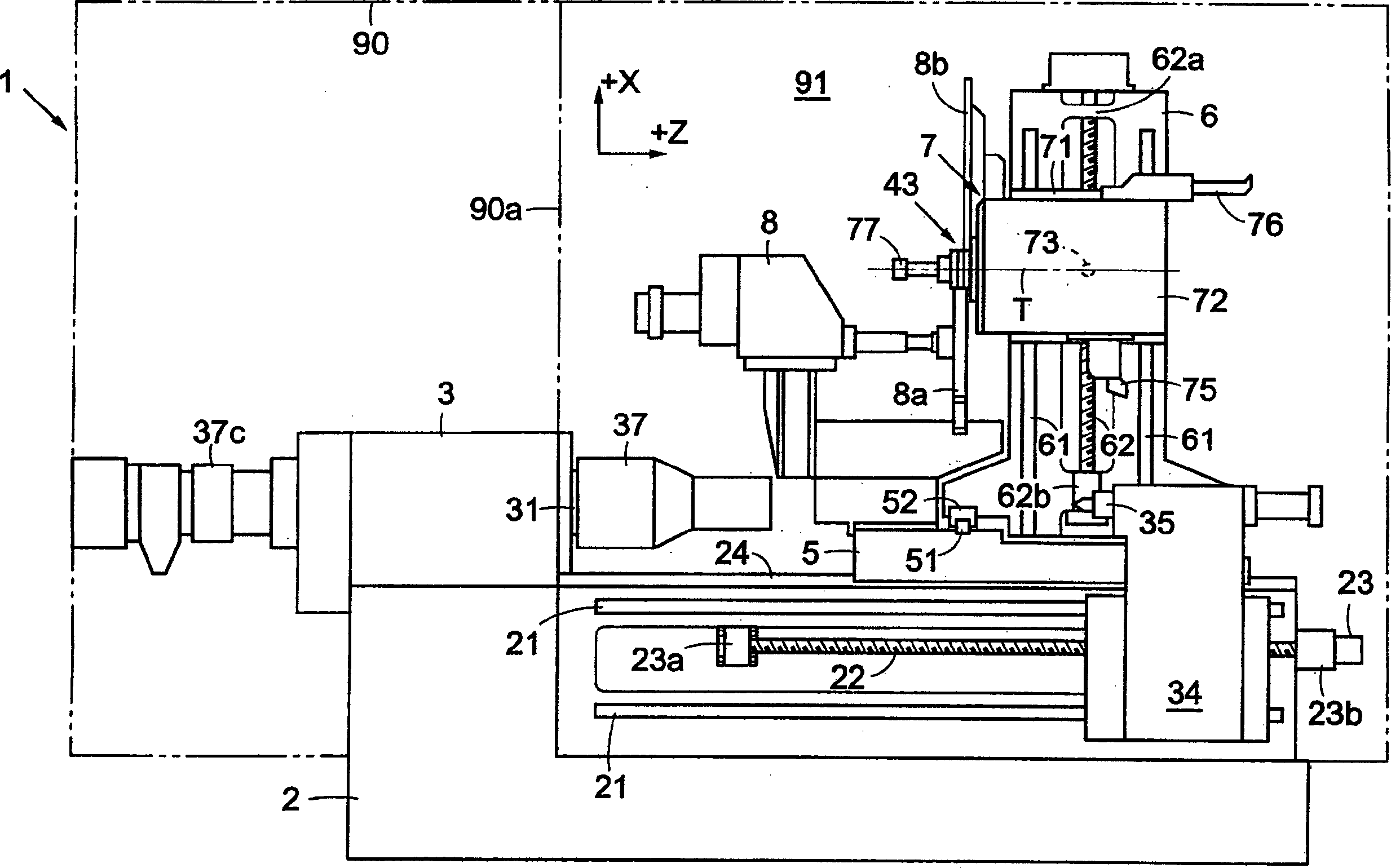
[0039] Embodiments of the present invention will be described with reference to the drawings. figure 1It is a figure which shows the whole structure of the compound processing machine tool 1 of this invention. A headstock 3 is fixedly arranged on a bed 2 serving as a base of the multi-function machine tool 1 . On the headstock 3, a spindle 31 for rotatably driving a workpiece is rotatably provided. The main shaft 31 is arranged such that its center axis becomes a horizontal direction, and the direction of the center axis is taken as the Z-axis direction of the Cartesian coordinate system.

[0040] Also, on the top end of the main shaft 31, a workpiece mounting mechanism 37 for mounting a workpiece is fixed. The spindle 31 is rotationally driven by a built-in spindle motor (not shown) in a state where a workpiece is mounted on the workpiece mounting mechanism 37 . In addition, the NC device (not shown) for controlling the rotary motion of the main shaft 31 has a function of ...


PUM


Abstract

The multi-function machine tool of the present invention has a tool rest main body which is disposed movably relative to the main spindle of the machine tool in a first linear direction parallel to the axial line of the main spindle and a second linear direction perpendicular to the axial line of the main spindle, a turning tool rest 72 which is disposed so that this turning tool rest can turn relative to the tool rest main body about a turning axis 73 oriented in a direction that is perpendicular to the first and second linear directions, and control means which control the rotational motion of the main spindle, the turning motion of the turning tool rest about the turning axis, and the relative motion of the tool rest main body. Furthermore, the control means can cause the turning tool rest to perform a turning motion about an arbitrary position that differs from the position of the turning axis by concurrently and synchronously causing a turning motion of the turning tool rest about the turning axis, and a circular-arc motion based on the relative motion of the tool rest main body in the first linear direction and second linear direction.

Description

[0001] technology area [0002] The present invention relates to a compound processing machine tool for processing a workpiece held on a workpiece mounting mechanism at the top of a rotatable spindle by a tool mounted on a rotary tool table capable of rotary motion and linear motion in more than two directions, and the compound processing machine tool The processing method of the invention relates in detail to a compound processing machine tool capable of processing spiral grooves of various shapes on a workpiece and a processing method in the compound processing machine tool. Background technique [0003] Techniques described in Patent Document 1, Patent Document 2, and the like described later are known as methods for machining complex-shaped spiral grooves in a workpiece. Patent Document 1 describes a method of machining a helical groove of a screw compressor by rotating a tool while rotating a tool. However, the machine tool for implementing this method is a special-purpo...

Claims


Application Information

Patent Timeline
Patent Type & Authority Applications(China)
IPC IPC(8): B23Q11/08B23B3/16B23B5/46B23B5/48B23B21/00B23C3/32B23F13/06B23F15/08B23P23/02B23Q1/62G06F19/00
CPCB23Q1/623B23F15/08B23B5/48Y10T82/2543Y10T483/1771B23P23/02
Inventor 上原正也柚原美和子
Owner MORI SEIKI HITECH
Why Eureka
Try Eureka