Ice machine

A technology for an ice maker and a casing, applied in the field of ice maker, can solve the problems of wasting water, prolonging the time required for freezing, high energy consumption, etc.

Inactive Publication Date: 2004-05-05
SAMSUNG GWANGJU ELECTRONICS CO LTD
View PDF1 Cites 25 Cited by
  • Summary
  • Abstract
  • Description
  • Claims
  • Application Information

AI Technical Summary

Problems solved by technology

[0012] Such conventional ice makers require more water than is actually frozen, and since the sink is designed to hold more water than is required to make ice cubes, a large amount of water directed into the water collection area 15 is wasted
[0013] In...

Method used


Image

  • Ice machine
  • Ice machine
  • Ice machine

Examples


Embodiment Construction

[0023] Hereinafter, an ice maker according to a preferred embodiment of the present invention will be described in more detail with reference to the accompanying drawings. where the same reference numerals indicate the same figure 1 with figure 2 The same parts as the parts of the prior art device.

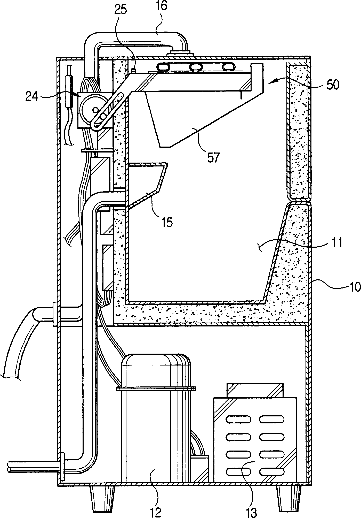
[0024] Such as image 3 with Figure 4 As shown, the ice maker of the present invention includes a cabinet 10 , a freezing unit 50 and an ultrasonic transducer 60 .

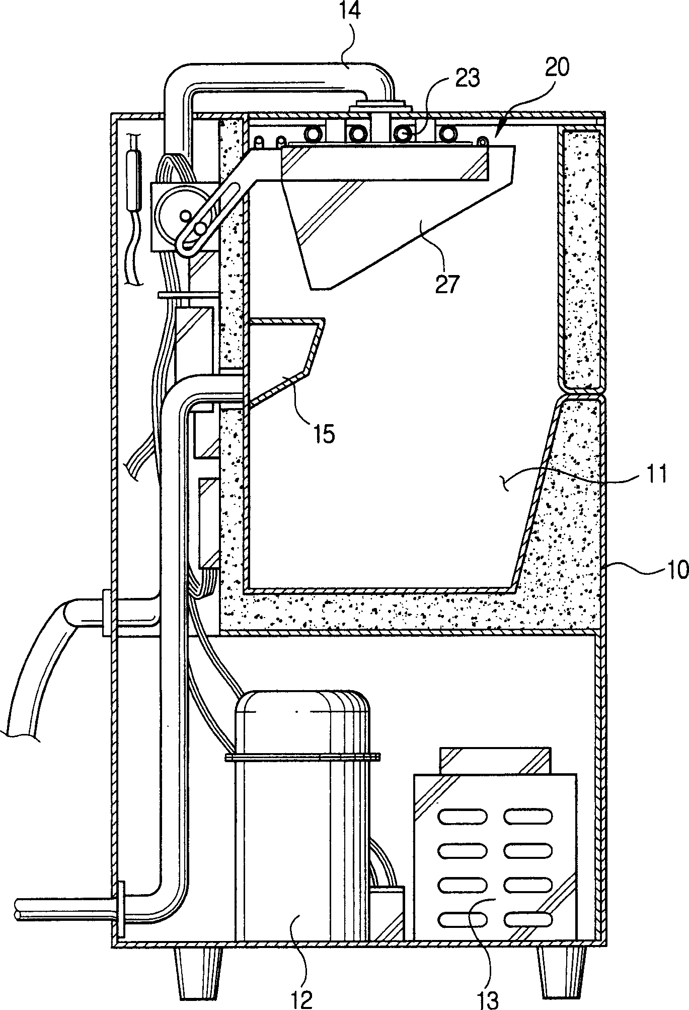
[0025] The cabinet 10 has an ice storage bin 11 for storing ice cubes generated by the freezing unit 50 . A compressor 12 including a freezing system and a condenser 13 are located below the ice storage bin 11, and a water collection area 15 is located at the side of the ice storage bin 11 for draining remaining water.

[0026] The freezing unit 50 includes a base frame 51 , a freezing base plate 52 and an evaporator 53 . The base frame 51 is pivotally positioned above the cabinet 10, and the base frame has a ...


PUM


Abstract

An ice making machine comprising a housing, an evaporator connected to a freezing system, a base frame having a lower surface and a multiplicity of freezing cells for retaining water to be frozen, a freezing base plate provided adjacent to the evaporator and the freezing base plate having freezing fingers formed on the lower surface of the freezing base plate to be dipped into the water retained by the freezing cells, and an ultrasonic transducer for removing air bubbles inside the water by vibrating the water contained in the freezing cells with ultrasonic waves. The ultrasonic transducer preferably is disposed on the lower surface of the base frame.

Description

technical field [0001] The present invention generally relates to an ice maker, and more particularly, to an ice maker capable of shortening the ice making time and minimizing the amount of wasted water. Background technique [0002] An ice maker is a device that makes ice cubes by freezing water supplied from an external water source. Recently, an ice maker capable of preventing cloudiness of ice cubes due to freezing of air bubbles in water has been proposed. [0003] figure 1 with 2 Shown is a conventional ice maker as disclosed in US Patent No. 5,425,243. Such as figure 1 with 2 As shown, a conventional ice maker includes a cabinet 10 , a freezing unit 20 and an air removal device 30 . [0004] The cabinet 10 of the ice maker includes an ice storage bin 11 for storing ice cubes made by the freezing unit 20 . The compressor 12 and the condenser 13 are placed below the ice storage bin 11 inside the cabinet 10 . [0005] Such as figure 2 As shown, the freezing uni...

Claims


Application Information

Patent Timeline
IPC IPC(8): F25C1/18F25C1/08F25C1/20F25C1/24
CPCF25C1/08F25C1/20F25C1/24
Inventor 金五福中條英穗
Owner SAMSUNG GWANGJU ELECTRONICS CO LTD
Why Eureka
Try Eureka