Time coupled packet transmission

A technology of time slot allocation and time division multiplexing, applied in time division multiplexing systems, time division multiplexing selection devices, electrical components, etc., can solve the problem of bandwidth redistribution, uninterrupted transmission, bandwidth waste, etc. question

Inactive Publication Date: 2004-05-12
PHYSICAL OPTICS CORP
View PDF0 Cites 3 Cited by
  • Summary
  • Abstract
  • Description
  • Claims
  • Application Information

AI Technical Summary

Problems solved by technology

This results in a portion of the allocated slots not being used
Therefore, the unused portion of the allocated slots creates a waste of bandwidth
[0004] Another problem in existing network equipment is that these equipment do not provide users with efficient reallocation of bandwidth
Furthermore, the use of packet-switched network equipment to transport TDM data poses the problem of delivering a continuous stream of data (such as video) without interruption

Method used


Image

  • Time coupled packet transmission
  • Time coupled packet transmission
  • Time coupled packet transmission

Examples


Embodiment Construction

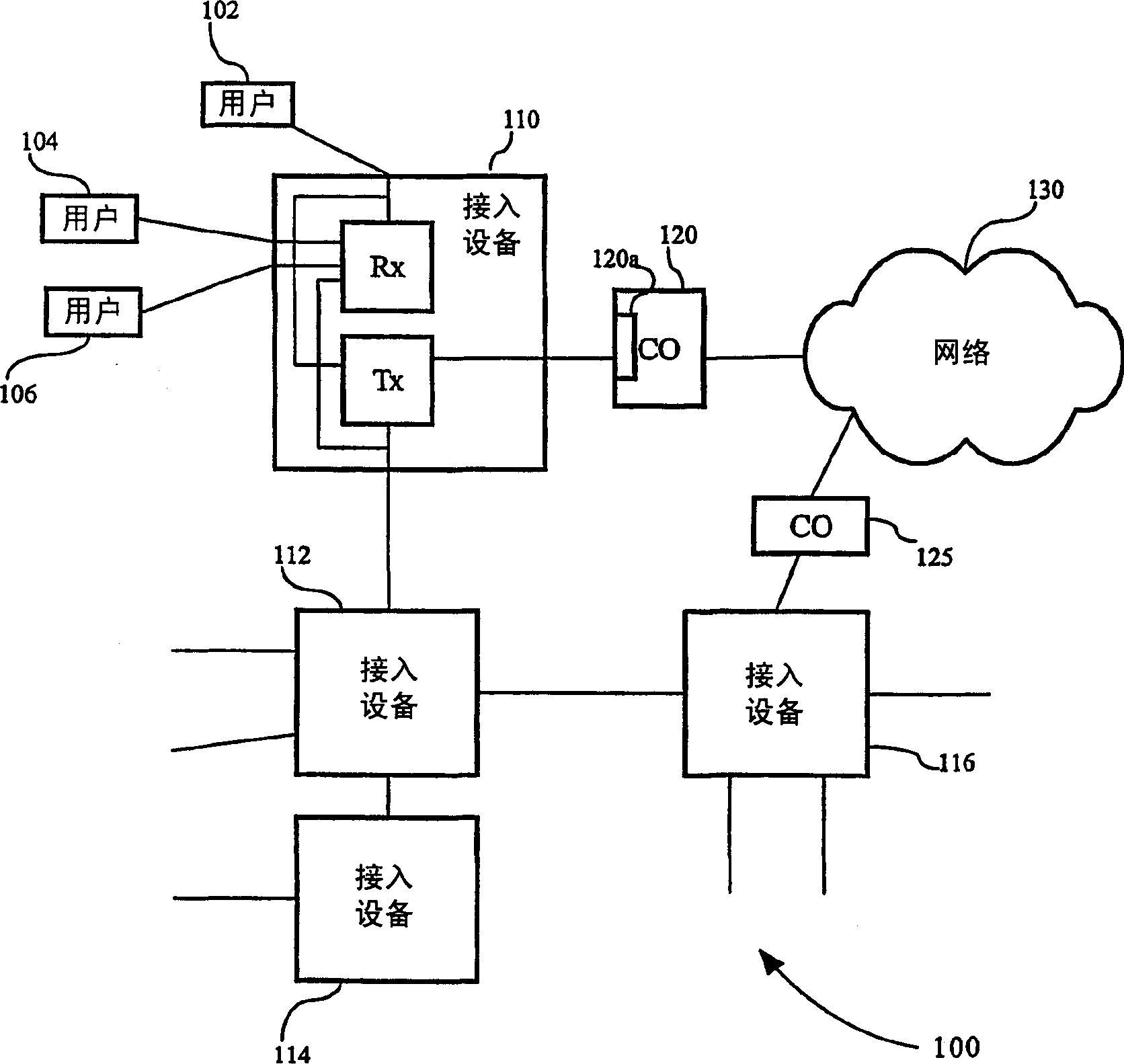
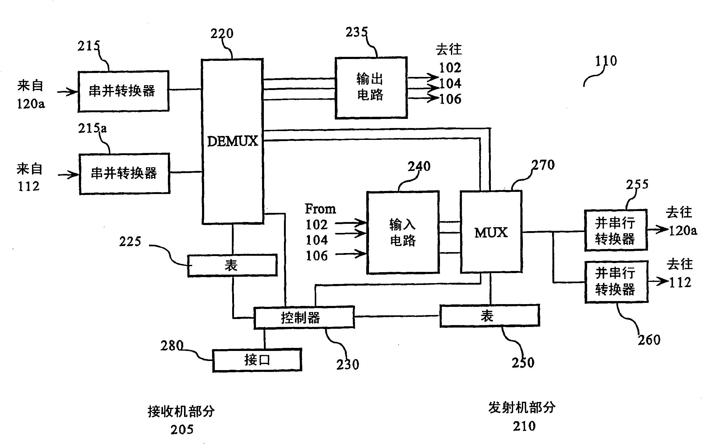
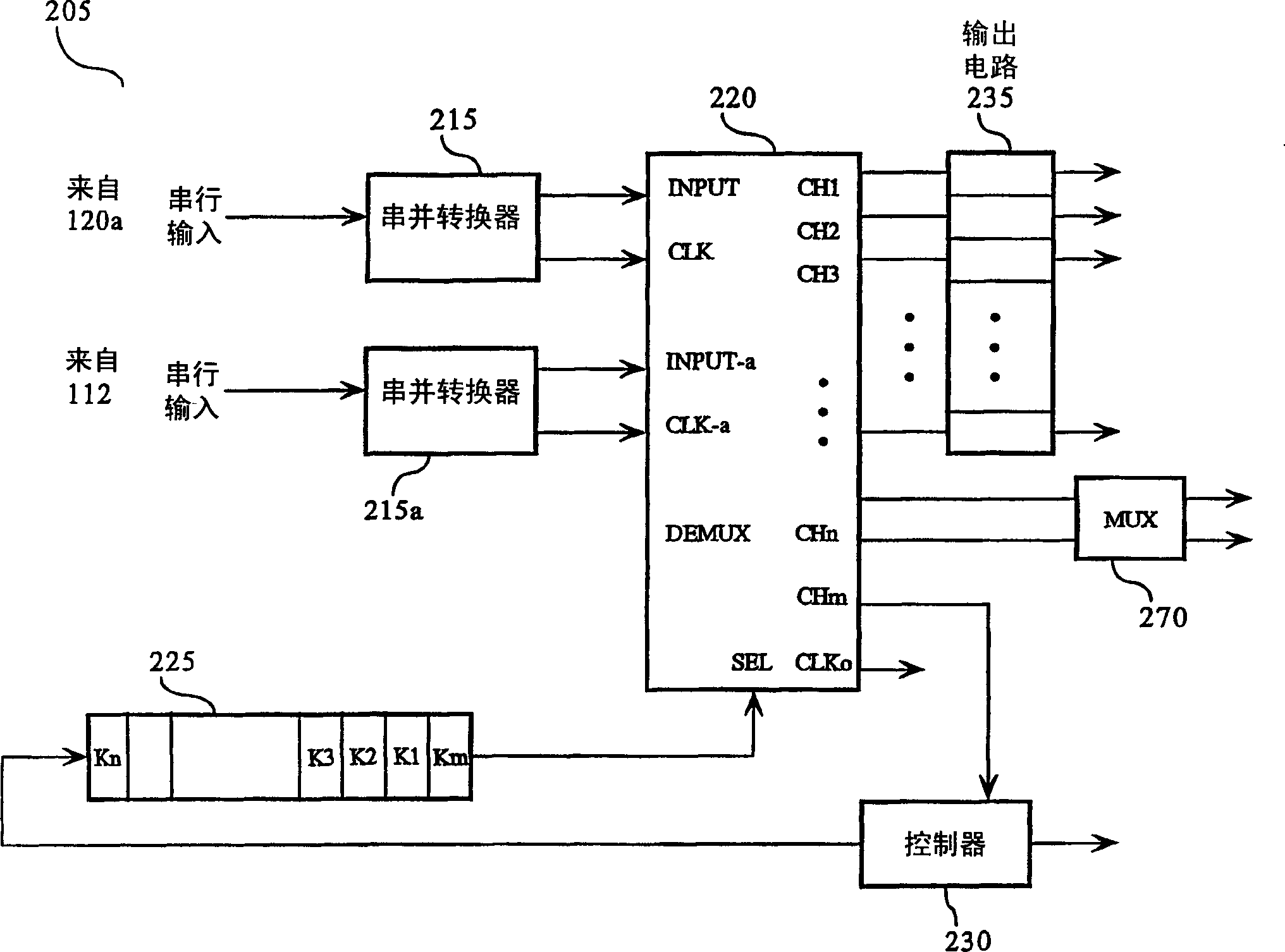
[0023] figure 1 is a representative illustration of a system 100 for accessing a network 130 in accordance with a preferred embodiment. The system 100 includes: users 102, 104, and 106; access devices 110, 112, 114, and 116; central offices 120 and 125; Users 102, 104, and 106 are users such as audio / video sources, data terminals, corporate local area networks, and the like. Central office 120 is such as a central office, point of presence, head end, or any other system that performs network data switching / routing functions or provides connectivity to a network. Typically, another access device 120a is located in the central office for connection to the access device 110 . Network 130 is a network such as a metropolitan area network, a wide area network, or any other network. System 100 provides interactivity between access devices.

[0024] The access device 110 acts as the boundary of the network 130 to send and receive data in multiple formats, including: telephony data...


PUM


Abstract

An access device (110) includes a timeslot allocation table (250) having timeslot allocation information, and a transmitter (210) coupled to the timeslot allocation table (250) for transmitting data and updated timeslot allocation information in accordance with the timeslot allocation information.

Description

technical field [0001] The invention relates to a method and device for accessing a network. Background technique [0002] Currently, network devices provide users with access to the Internet. For example, the user accesses the wide area network through the user's network equipment and the network equipment located in the central office. In addition, users access LAN and MAN through network equipment. For example, a user may use a network device based on time division multiplexing (TDM) (such as T1 or video), or a network device based on packet switching (such as Ethernet) to access the network. [0003] Unfortunately, network equipment does not provide users with an optimal allocation of bandwidth, time slots, and clock cycles. For example, a user is allocated a time slot of fixed duration, or multiple time slots of fixed duration, irrespective of the user's specific needs. In particular, the user may only need a part of the time slots, or a non-integer multiple of the ...

Claims


Application Information

Patent Timeline
Patent Type & Authority Applications(China)
IPC IPC(8): H04J3/16
CPCH04J3/16
Inventor 弗雷迪·林林·沙弗兰克·田杜克·德兰
Owner PHYSICAL OPTICS CORP
Why Eureka
Try Eureka