
Vehicle seat reclining device

A technology of seat and guiding device, which is applied in the direction of movable seats, chairs, reclining chairs, etc., and can solve problems such as balance

Inactive Publication Date: 2004-05-19
TF METAL CO LTD
View PDF2 Cites 21 Cited by
  • Summary
  • Abstract
  • Description
  • Claims
  • Application Information

AI Technical Summary

Problems solved by technology

However, this inward force cannot be balanced solely by the frictional force between the guide surface and the fixed surface pressed against it.

Method used


Image

  • Vehicle seat reclining device
  • Vehicle seat reclining device
  • Vehicle seat reclining device

Examples


Embodiment Construction

[0035] Below, combined with Figures 1 to 20 Embodiments of the present invention are described by way of example.

[0036] (first embodiment)

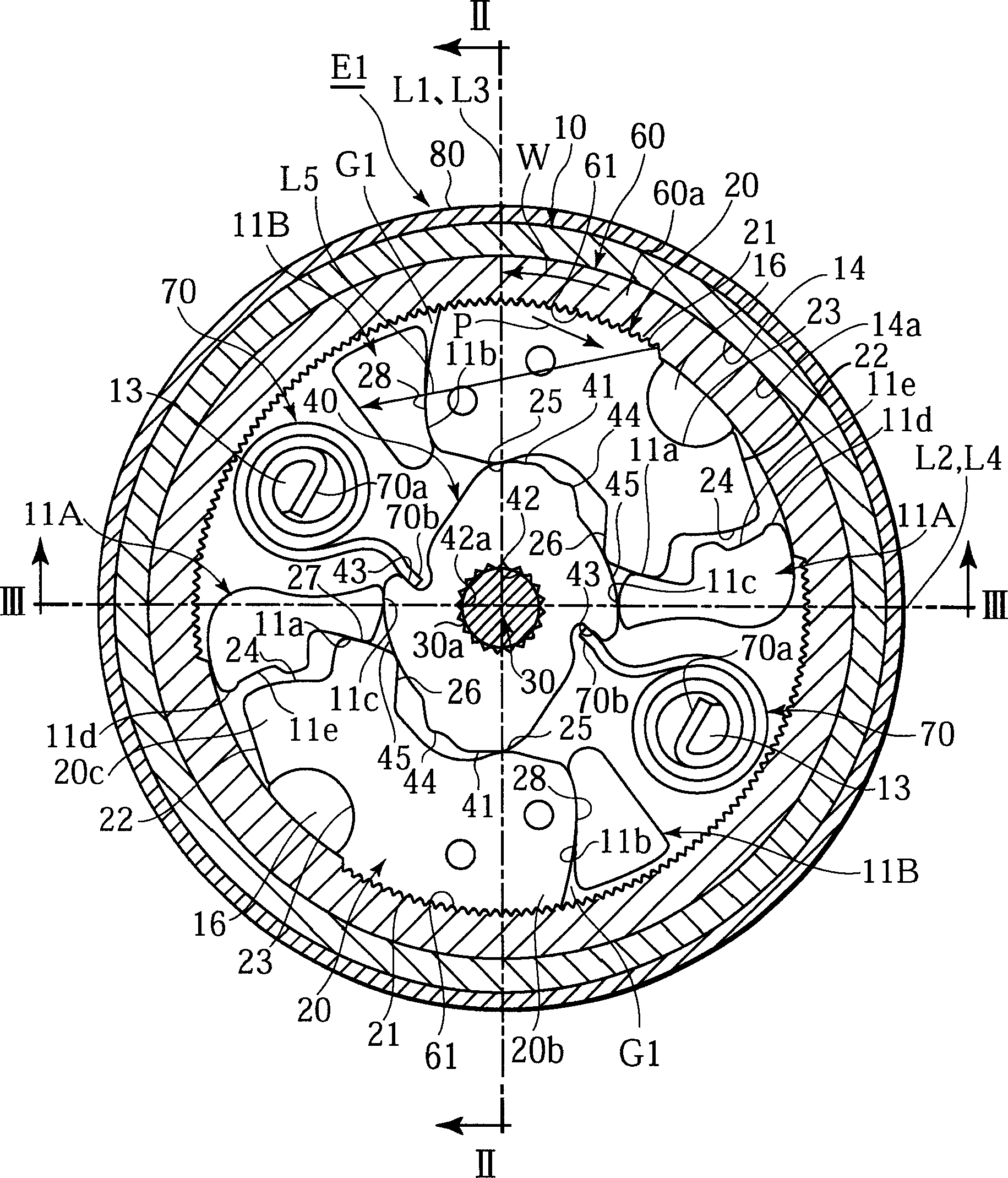
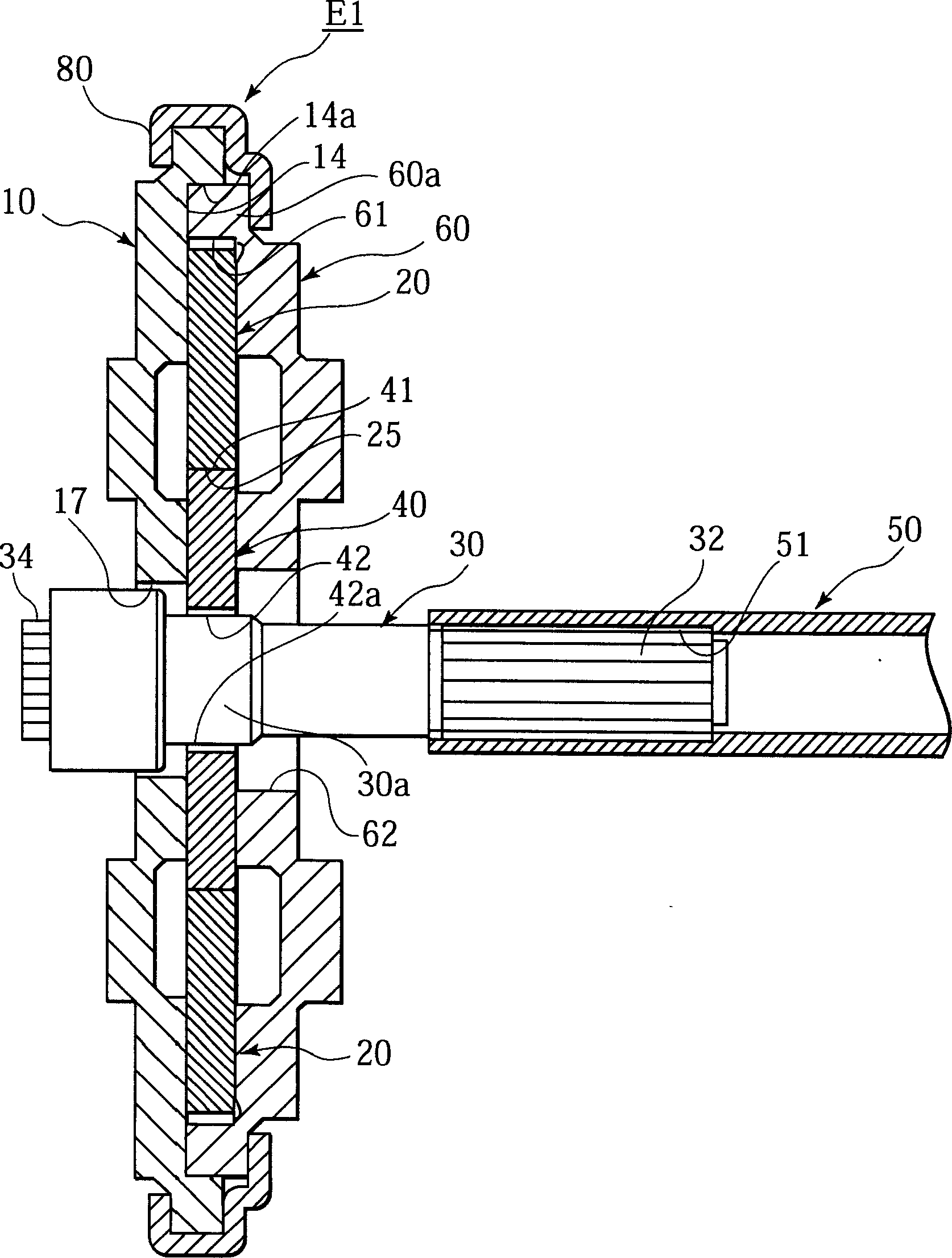
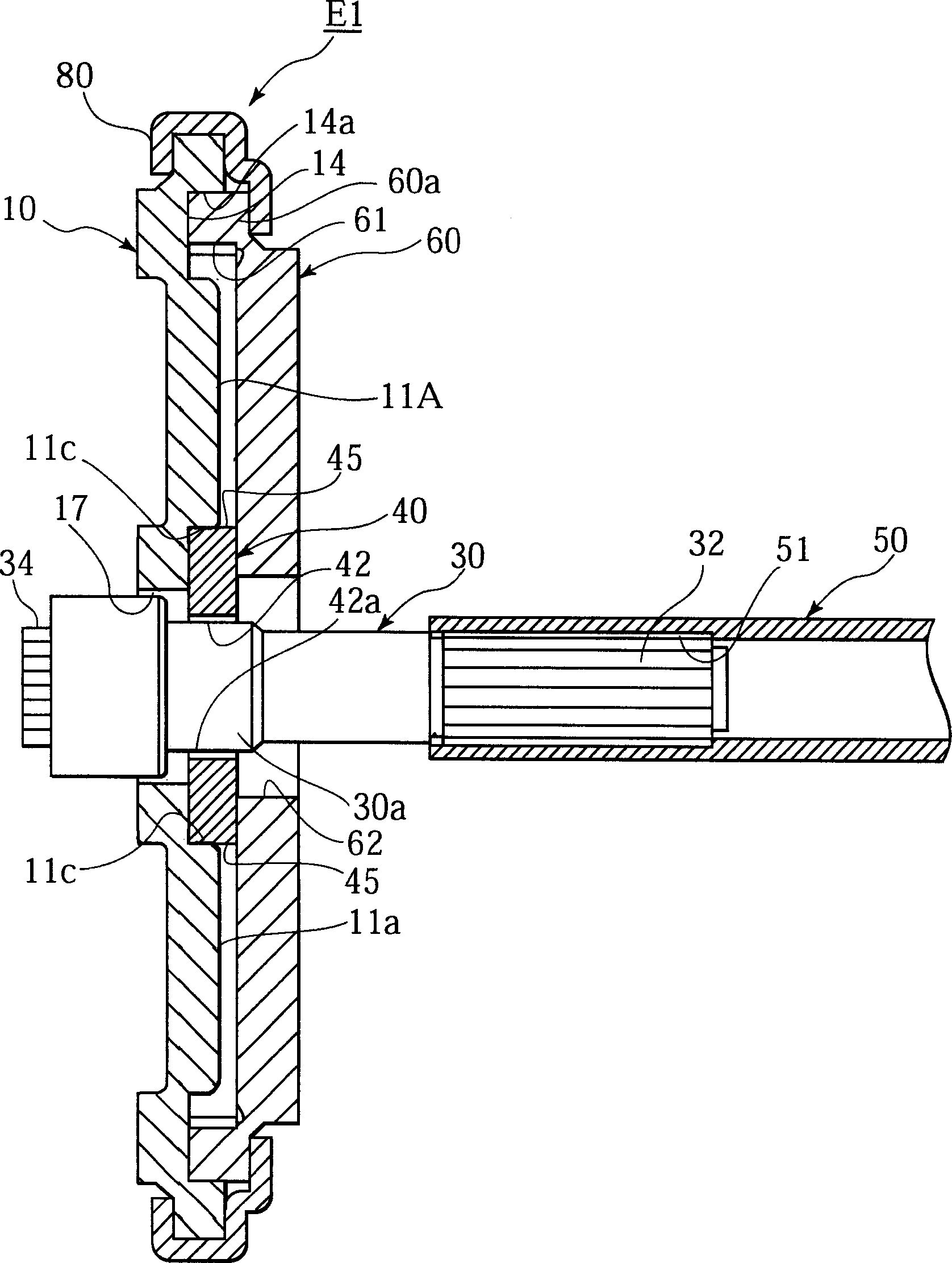
[0037] combined with Figures 1 to 11 The vehicle seat reclining device E1 of the first embodiment will be described. The seat recliner E1 includes a cover 60 fitted onto the inner surface of the circular recess 14 of the frame 10 . The cover 60 is coaxially rotatable along the inner circumferential surface of the groove 14 . The seat recliner E1 includes a rotatable or pivotable locking member 20 and a rotatable cam plate or cam 40 . Both pieces 20, 40 are arranged between the frame 10 and the cover 60 in the axial direction.

[0038] The cover 60 includes internal gears 61 at two opposite positions along its inner circumference. The locking member 20 is mounted on the frame 20 for rotation about the pivot 16 at two locations. The locking member 20 includes an external gear (teeth) 21 disposed facing each internal gear 61 . T...


PUM


Abstract

The seat recliner includes a base (10) mounted to a first seat member. The seat recliner includes a gear (60) mounted to a second seat member and being rotatable relative to the base. The gear has first teeth (61) along a peripheral face of the gear. The seat recliner includes a locking member (20) movable inside of the first teeth. The locking member has second teeth (21) engageable with the first teeth. The seat recliner includes a cam (40) configured to rotate the locking member to engage the first and second teeth with each other for establishing an angle between the first and second seat members. The seat recliner includes a guide (11B) on the base and having a guide face (11b) for slidably guiding the locking member to engage the first and second teeth with each other. The guide extends radially from a vicinity of the first teeth to a vicinity of the cam. A near side of the guide relative to the first teeth and the locking member define a gap (G1) therebetween.

Description

technical field [0001] The present application relates to a vehicle seat reclining device for rotatably mounting a seat back serving as a backrest relative to a seat pad serving as a seat surface. Background technique [0002] A vehicle seat recliner of this type includes a frame, for example, which is mounted on a floor at the side of the seat cushion. The seat recliner consists of a cover that fits over the arm panel of the seat back. The frame and cover are made rotatable relative to each other. The external gear (teeth) of the locking member on the frame engages (ie meshes) with the internal gear on the inner peripheral surface of the cover. This engagement prevents relative rotation between the frame and cover, thereby supporting the seat back in position at a given angle. For this, reference can be made, for example, to Japanese Unexamined Patent Publication Nos. 2002-10847 and 2002-291563. [0003] In the frame, pivots and guides are provided in the vicinity of th...

Claims


Application Information

Patent Timeline
IPC IPC(8): A47C1/025B60N2/20
Inventor 松浦宽大庭彻也
Owner TF METAL CO LTD
Learn More