Weft throwing nozzle of fluid spraying type weaving machine

A technology of fluid jetting and nozzles, applied in the directions of looms, jetting devices, jetting devices, etc., can solve the problems of increasing fabric defects due to diffusion, and the connection of gap size without any discussion.

Active Publication Date: 2004-05-19
TSUDAKOMA KOGYO KK
View PDF1 Cites 1 Cited by
  • Summary
  • Abstract
  • Description
  • Claims
  • Application Information

AI Technical Summary

Problems solved by technology

Therefore, there is a problem that when the jet is formed into a shape other than a perfect circle, the diffusion increases, or it collides with the warp opening to form a fabric defect (vertical streak)
[0006] In addition, in the above-mentioned prior art, for the gap size between the rectifying blades on

Method used


Image

  • Weft throwing nozzle of fluid spraying type weaving machine
  • Weft throwing nozzle of fluid spraying type weaving machine
  • Weft throwing nozzle of fluid spraying type weaving machine

Examples


Embodiment Construction

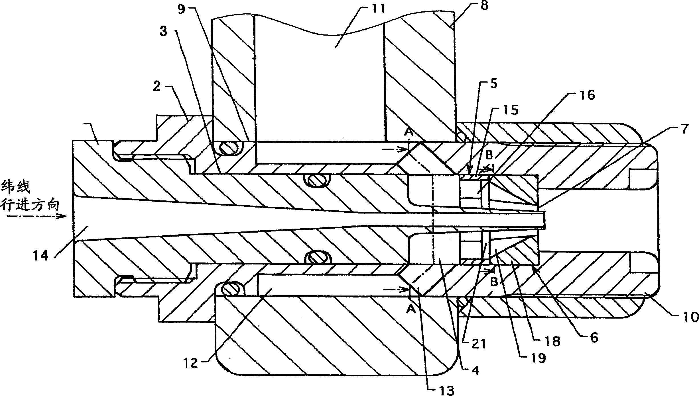
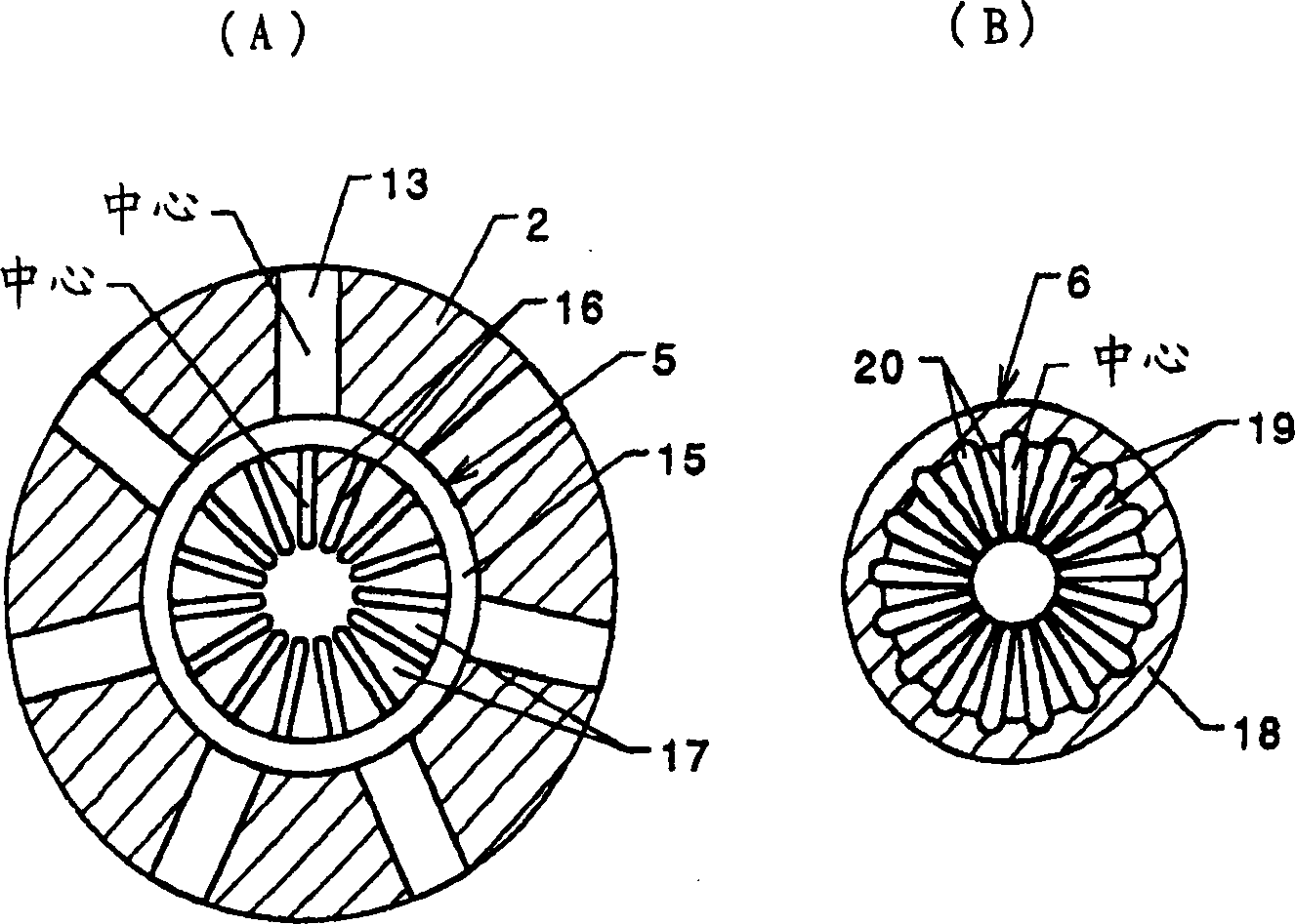
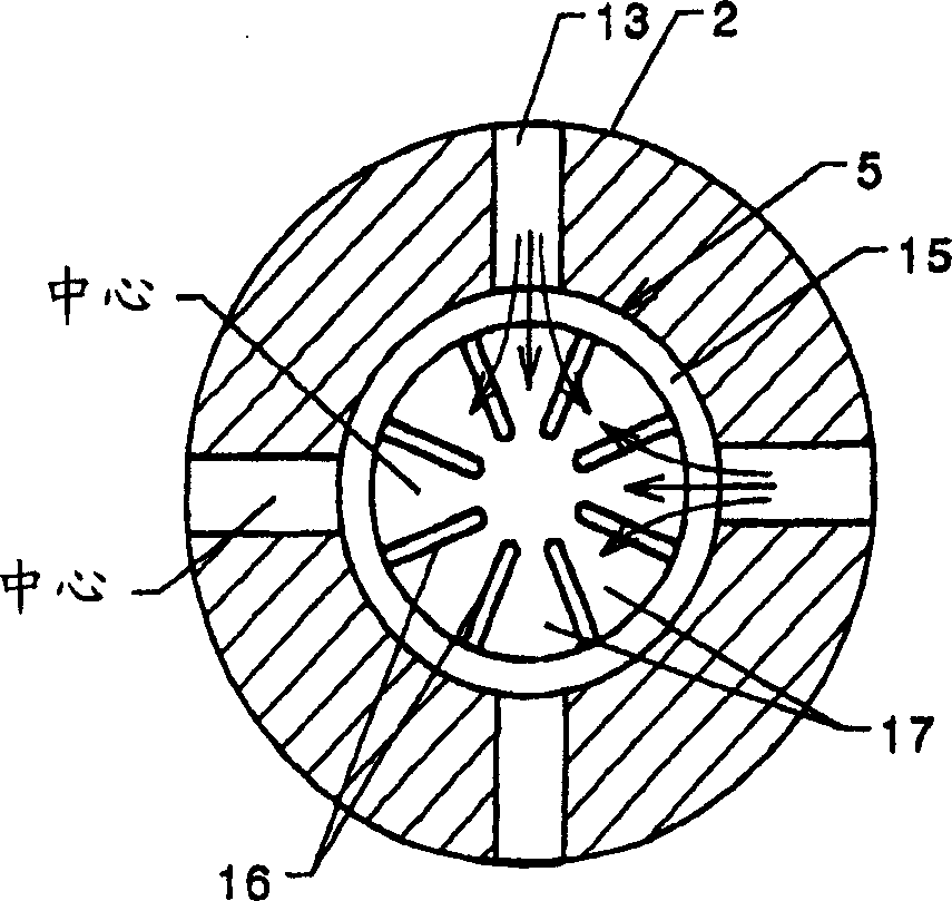
[0043] Such as figure 1 As shown, the weft throwing nozzle of the fluid jet loom inserts the knitting needle 1 into the hollow part 3 of the nozzle body 2, and an annular flow path is formed between the front part of the knitting needle 1 and the nozzle body 2. The rear part of the flow path is used as the annular chamber 4, and the first and second rectifying members 5, 8 are sequentially arranged in the front part of the flow path and along the weft traveling direction. Between the first and second rectifying members 5, 6 and the knitting needles A flow path is formed therebetween, and a fluid injection hole 7 is formed between the knitting needle 1 and the tip of the second rectifying member 6. The nozzle body 2 is inserted into the insertion hole 9 at the front of the nozzle holder 6 formed in a cylindrical shape, and the nozzle cover 10 is screwed onto the outer side of the front of the nozzle body 2 to fix the nozzle body 2 to the nozzle holder. 8, an annular groove 12 comm...


PUM


Abstract

To optimize a space dimension between a rectifying fin on upstream side and a rectifying fin on downstream fin and a relationship between the number of a water supply hole and the number of rectifying grooves while optimizing the number of the rectifying grooves of a plurality of rectifying members of a weft-inserting nozzle. The weft-inserting nozzle of the fluid jetting type loom comprises a needle 1, a nozzle body 2 in which a water supply hole 13 formed in a hollow shape and passing through a hollow part 3 is provided and the needle is inserted into the hollow part 3 and a circular chamber 4 made to communicate with the water supply hole is constituted between the top of the needle 1 and the nozzle body 2, and a plurality of rectifying fins 5 and 6 arranged in the circular chamber in turn in the advancing direction of weft. Each rectifying fin has a plurality of rectifying passages 17, 30 and 20 provided at equal spaces in the circumferential direction and each extending to the shaft direction. In the weft-inserting nozzle of the fluid jetting type loom, the number of each rectifying passage of a first rectifying member and a second rectifying member is kept to >=6 and <=40 and mutually has no common denominator.

Description

Technical field [0001] The invention relates to a weft throwing nozzle of a fluid jet loom. Background technique [0002] As the weft throwing nozzle of a conventional fluid jet loom, a knitting needle is inserted into the nozzle body, an annular flow path is formed between the tip of the knitting needle and the nozzle body, and two rectifying members are arranged in the flow path , In the nozzle body, an appropriate number of water supply holes are provided on the upstream side of the flow path, and fluid is sprayed from the jet hole between the downstream side rectifying member and the knitting needle. In addition, the rectification member has a cylindrical shape as a whole, and radial rectification vanes are arranged at equal intervals in the circumferential direction to allow fluid to pass through the rectification grooves formed between adjacent rectification vanes. Therefore, the rectification of the upstream rectification member The number of blades is 16, and the number o...

Claims


Application Information

Patent Timeline
IPC IPC(8): D03D47/32
CPCB05B1/06D03D47/32D03D49/50D03J1/04
Inventor 服部恒一
Owner TSUDAKOMA KOGYO KK
Why Eureka
Try Eureka