Foreign matter removing mechanism, foreign matter removing method, printing device and printing method

A technology of a printing device and a printing method, which can be applied to projection devices, cameras, projectors with built-in screens/external-mounted screens, etc., can solve the problems of easily rolling in foreign objects, increase manufacturing costs, etc., to suppress adhesion and reduce charging bias. , the effect of reducing the charged gap

Inactive Publication Date: 2004-05-19
SHARP KK
View PDF7 Cites 8 Cited by
  • Summary
  • Abstract
  • Description
  • Claims
  • Application Information

AI Technical Summary

Problems solved by technology

[0036] However, for the technology of document ⑥, because it is necessary to install an air flow generating device, there is a disadvantage of increasing the manufacturing cost.
[0037] And, for the technology of document ⑦, the charging roller should be set so that its rotation direction is opposite to that of the photoreceptor drum (the opposite surface moves in the same direction), so there is an easy existence between the charging roller and the photoreceptor drum. The problem of getting caught in foreign matter

Method used


Image

  • Foreign matter removing mechanism, foreign matter removing method, printing device and printing method
  • Foreign matter removing mechanism, foreign matter removing method, printing device and printing method
  • Foreign matter removing mechanism, foreign matter removing method, printing device and printing method

Examples


Embodiment 1

[0111] An embodiment of the present invention will now be described.

[0112] The printing device (this printing device) of this embodiment is a printing device of an electronic imaging system that prints an image corresponding to image data on paper (printing paper) using a two-component developer including toner and a carrier. . In addition, the developing method of this printing device is reverse developing.

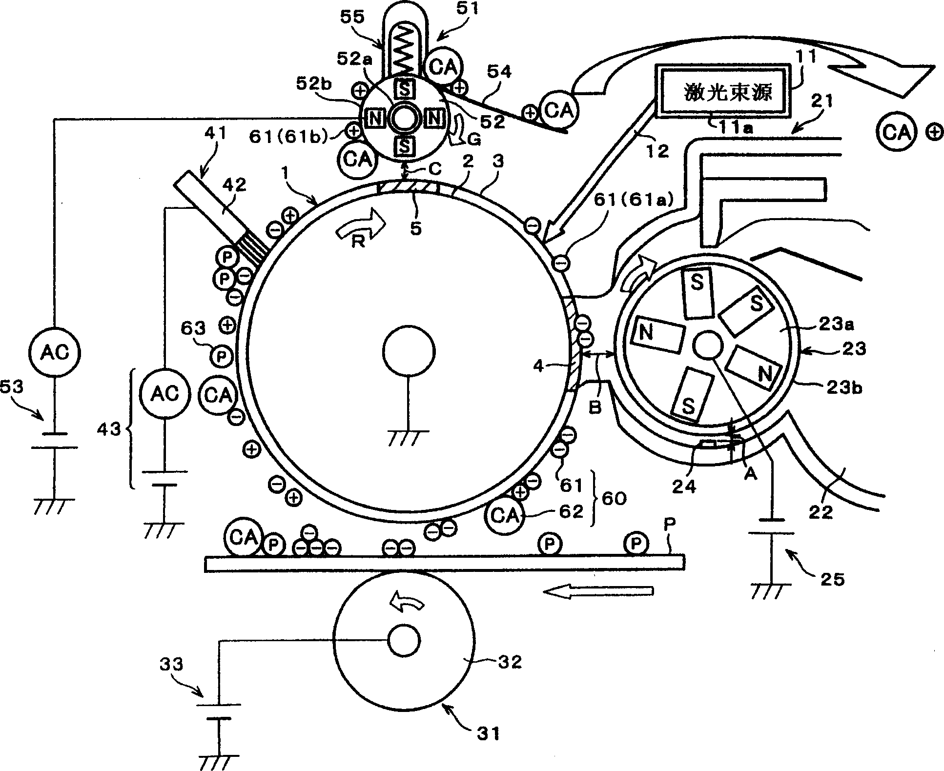
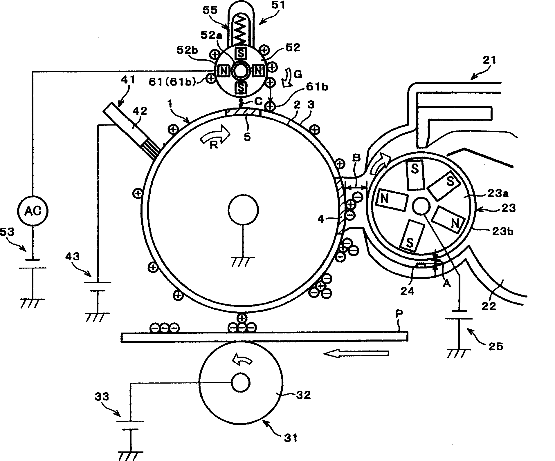
[0113] figure 1 It is an explanatory diagram showing the configuration of this printing apparatus.

[0114] As shown in the figure, the structure of this printing apparatus is: around the photoreceptor 1, starting from the exposure position (irradiation position where the laser light 12 is emitted from the LSU11), along the rotation direction of the photoreceptor 1, the LSU11, the developing device 21 , transfer device 31 , foreign matter stirring device 41 , and charging device 51 .

[0115] The photoreceptor (image holder) 1 is a photoreceptor drum rotationally...

Embodiment 2

[0604] Another embodiment of the present invention will be described below.

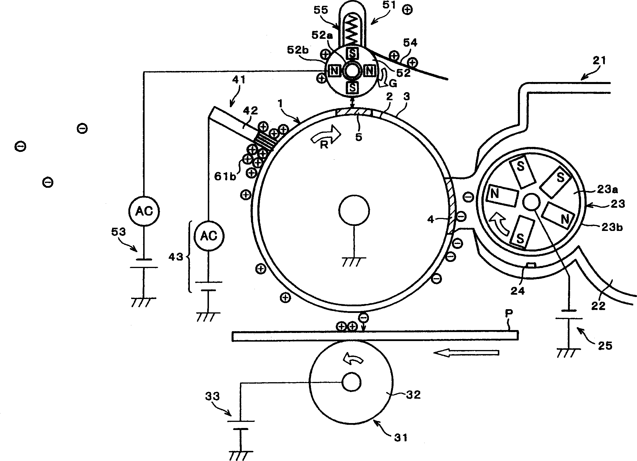
[0605] In the above-mentioned Embodiment 1, a printing apparatus employing a two-component development method in which a two-component developer containing the toner 61 and the carrier 62 is used was exemplified. In this embodiment, a printing apparatus adopting a one-component developing method, in which a one-component developer not containing the carrier 62 is used, is exemplified instead of a two-component developing method. In this embodiment, differences from the first embodiment described above are mainly described. For the convenience of description, the same reference numerals are given to components having the same functions as those in the first embodiment, and their descriptions are omitted.

[0606] Figure 15 It is an explanatory diagram showing the configuration of the printing apparatus (this printing apparatus) of this embodiment. As shown in the figure, in this printing apparatus...


PUM


Abstract

The present removing system has an object to remover a left-over toner that is accumulated on a brush that touches a left-over toner on a photoreceptor. More specifically, the present removing system is so arranged that an alternating voltage (superimposing voltage) on which a positive direct current voltage is superimposed is applied onto a conductive brush in accordance with a user's instruction. With this arrangement, even if a positively electrified left-over toner is accumulated on the conductive brush, it is possible to remove the positively electrified left-over toner accumulated on the conductive brush, because a voltage value (positive) applied on the conductive brush in a moment is large. Moreover, because a voltage of the conductive brush becomes negative in a moment, it is possible to remove a negatively electrified left-over toner attached on the conductive brush.

Description

technical field [0001] The present invention relates to a foreign matter removal mechanism for removing foreign matter remaining on a carrier in an electrographic printing device, a printing device equipped with the foreign matter removal mechanism, and a foreign matter removal method used in the foreign matter removal mechanism. Background technique [0002] In a printing apparatus (image forming apparatus) of an electrographic imaging system, a photoreceptor drum (image holder) is generally charged and exposed to form an electrostatic latent image, which is developed with a toner to form a toner image. Moreover, printing has been performed by transferring this toner image onto paper (copy material). [0003] There are roughly one-component and two-component developing materials for the developing materials used in such printing devices. [0004] The two-component developing material includes a carrier composed of magnetic materials such as Fe (iron) and ferrite in additio...

Claims


Application Information

Patent Timeline
Patent Type & Authority Applications(China)
IPC IPC(8): G03G21/00
CPCG03G21/0035G03G2221/0063
Inventor 富田章嗣加藤敦之恩田裕向井崇石井洋
Owner SHARP KK
Why Eureka
Try Eureka