Cooking fume purifier for kitchen and used adsorption liquid
A fume purifier, kitchen technology, applied in chemical instruments and methods, use of liquid separation agent, separation of dispersed particles, etc., can solve problems such as the scope of application is not too wide
- Summary
- Abstract
- Description
- Claims
- Application Information
AI Technical Summary
Problems solved by technology
Method used
Image

Examples
Embodiment 1
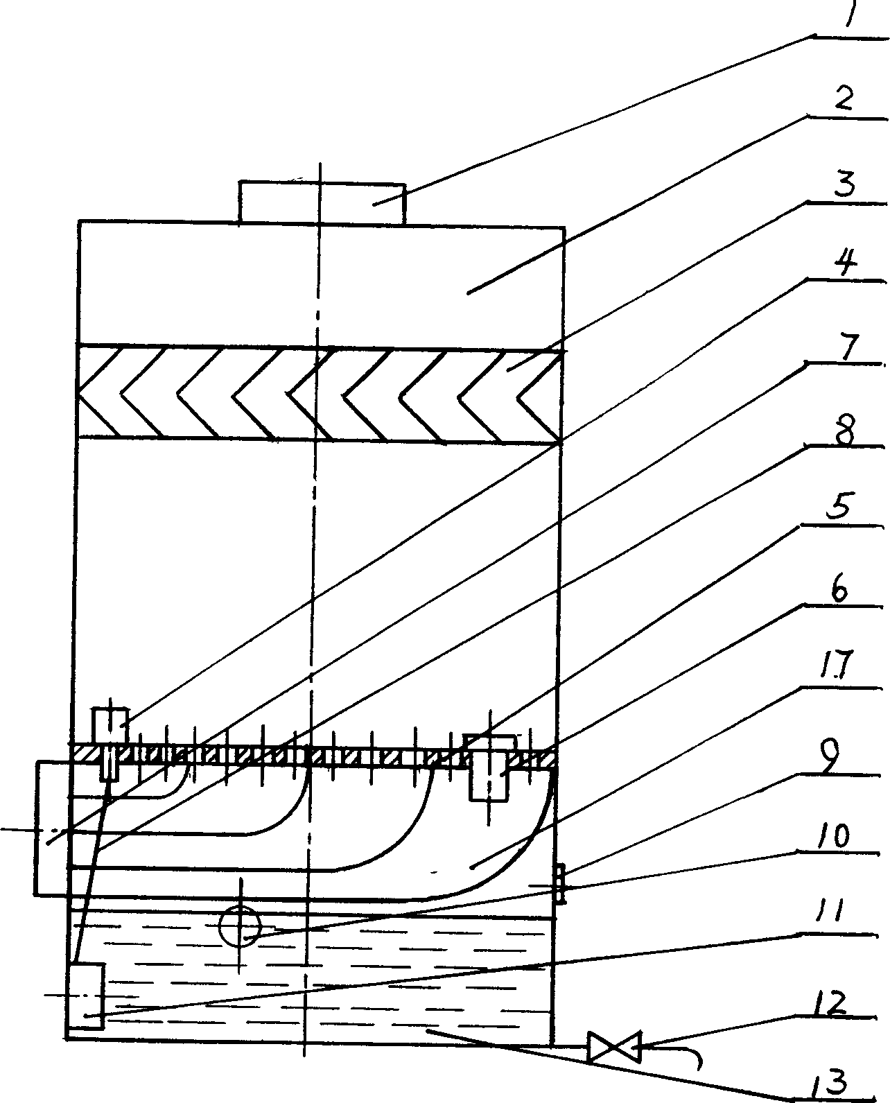
[0035] Example 1, see figure 1 , the present embodiment is for the situation that the velocity of the oil mist drop before entering the foam generator 5 is greater than the velocity of the airflow during foam purification. The shell of the purifier is made into a tower body 2 with a rectangular cross section. A foam generator 5 is fixed horizontally in the airflow channel between the air inlet 7 and the exhaust outlet 1 of the tower body 2. The foam generator 5 is a horizontal porous sieve plate, and the oil fume gas to be purified enters from the air inlet 7. In the tower, in order to make the fume flow generate more uniform foam on the foam generator 5, a flow trap 17 is installed between the air inlet 7 and the foam generator 5. The oil fume airflow passes upwards through the numerous small holes of the foam generator 5, forming strongly moving and extremely unstable foam on the surface of the continuous adsorption liquid 13, and the foam moves upward to complete the adsor...
Embodiment 2
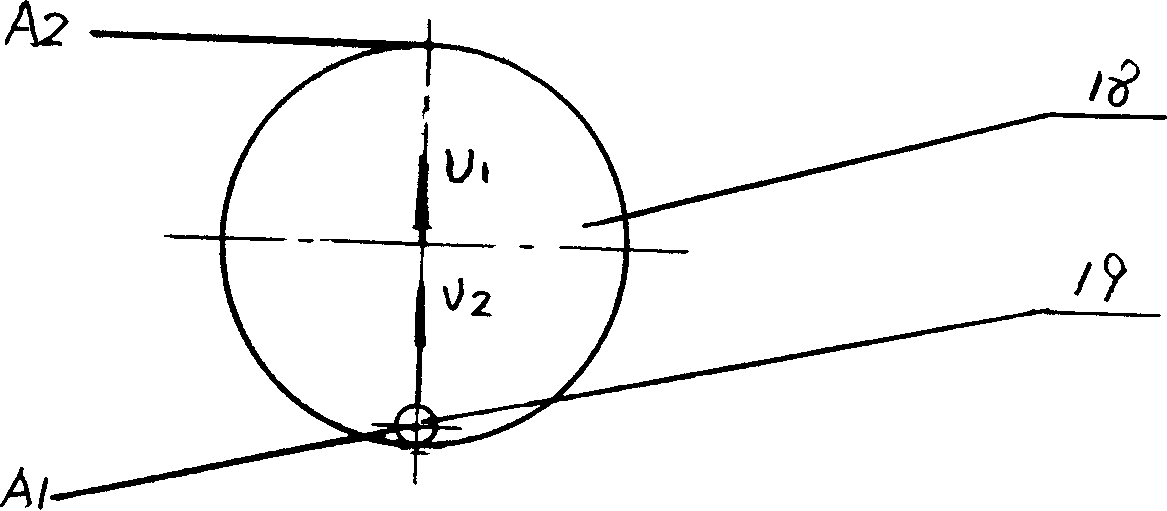
[0067] Example 2, see Image 6 , the present embodiment is the situation that the speed of the oil mist drop before entering the hole of the foam generator 5 is smaller than the airflow velocity behind the foam generator 5. The shell of the purifier is made into a tower body 2 with a rectangular cross section. In the air passage between the air inlet 7 of tower body 2 and the exhaust port 1, be obliquely fixed with foam generator 5, foam generator 5 is the same perforated sieve plate with foam generator 5 among the embodiment 1, The difference is that the former is installed horizontally and the latter is installed obliquely. At the beginning of work, firstly, the adsorption liquid 13 installed in the pool at the bottom of the tower body 2 is lifted by the pump 11, and passes through the pipeline 8 and the throttle valve 14 therein. The square overflow port 4 flows into the top of the foam generator 5 evenly from front to back, and under the pressure of the rising oil fume f...
Embodiment 3
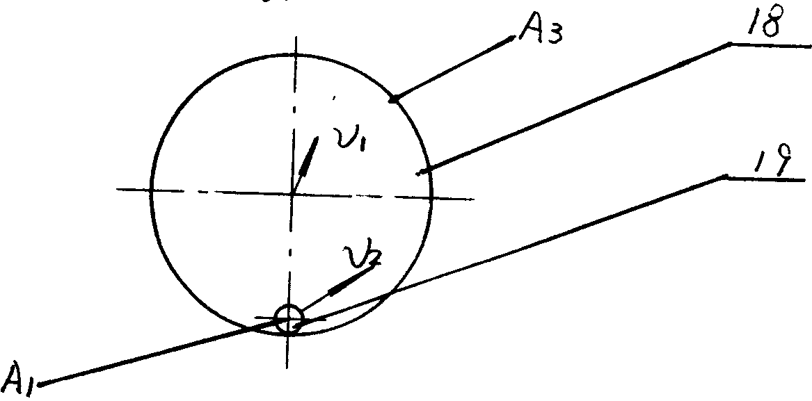
[0068] Embodiment 3, referring to Fig. 7 (this equipment non-working state figure) and Figure 8 (C of Fig. 7 is to working state figure), present embodiment is the situation that the speed of the oil mist drop that enters the hole of foam generator 5 hole system is greater than the speed of the air-flow behind foam generator. The shell of the purifier is made into a tower body 2 with a rectangular cross section. A foam generator 5 is fixed in the airflow channel between the air inlet 7 and the exhaust port 1 of the tower body 2. The foam generator 5 is a system composed of a plurality of porous pipes 31, and the axis lines of these holes are on the same horizontal plane. Inside, the fume gas to be purified enters the tower from the air inlet 7, moves downward to the bottom of the tower on the left, and then moves laterally into the multiple porous pipes 31 of the foam generator 5. Due to the effect of the air pressure of the fume gas flow, In the multiple porous pipes 31 of ...
PUM
| Property | Measurement | Unit |
|---|---|---|
| Depth | aaaaa | aaaaa |
| Size | aaaaa | aaaaa |
| Size | aaaaa | aaaaa |
Abstract
Description
Claims
Application Information
 - R&D
- Intellectual Property
- Life Sciences
- Materials
- Tech Scout
- Unparalleled Data Quality
- Higher Quality Content
- 60% Fewer Hallucinations
Browse by: Latest US Patents, China's latest patents, Technical Efficacy Thesaurus, Application Domain, Technology Topic, Popular Technical Reports.
© 2025 PatSnap. All rights reserved.Legal|Privacy policy|Modern Slavery Act Transparency Statement|Sitemap|About US| Contact US: help@patsnap.com