Supercharge Your Innovation With Domain-Expert AI Agents!

Output component structure for magnetron

A technology of output components and magnetrons, which is applied in the field of magnetrons, can solve the problem of low attenuation ability of the third high-frequency wave, and achieve the effect of improving attenuation ability

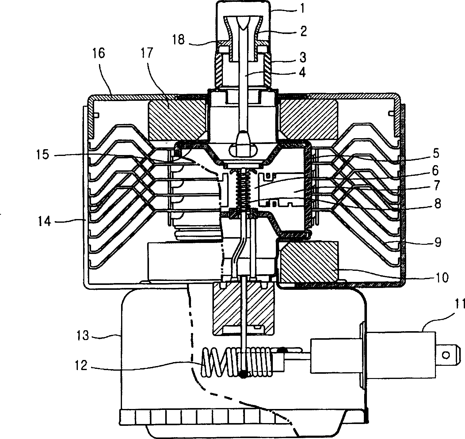
Inactive Publication Date: 2004-06-09
LG ELECTRONICS (TIANJIN) APPLIANCES CO LTD
View PDF0 Cites 2 Cited by
  • Summary
  • Abstract
  • Description
  • Claims
  • Application Information

AI Technical Summary

Problems solved by technology

That is to say, it leads to the problem that the attenuation ability of the third high-pitched wave is low

Method used


Image

  • Output component structure for magnetron
  • Output component structure for magnetron
  • Output component structure for magnetron

Examples


Embodiment Construction

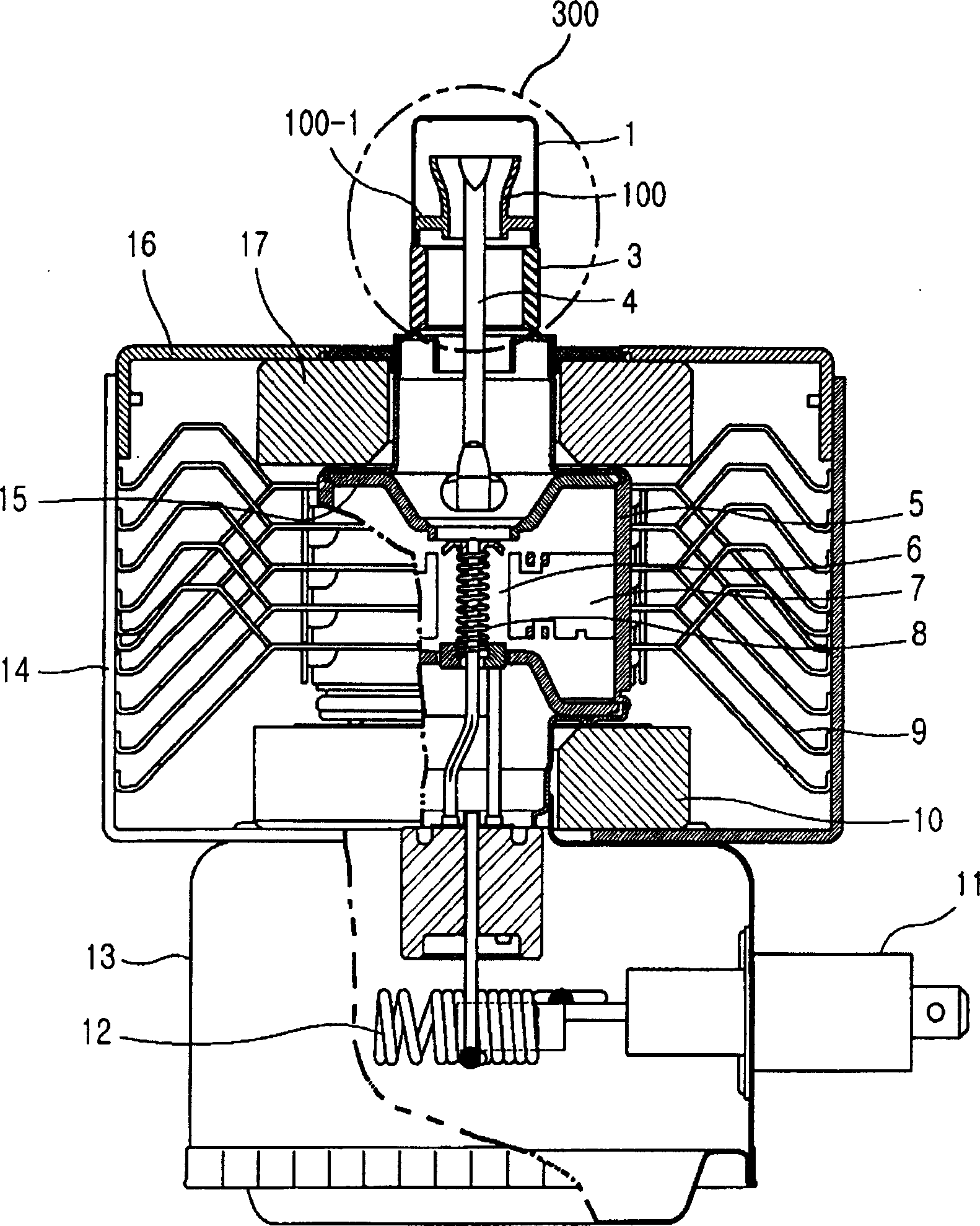
[0037] Refer to the attached Figure 3-7, the embodiment of the structure of the magnetron output part that improves the attenuation capability of the third high-frequency band by adjusting the length of the exhaust pipe of the magnetron output part of the present invention will be described in detail.

[0038] image 3 A cross-sectional view of a magnetron of the present invention is shown.

[0039] Such as image 3 As shown, the magnetron generally includes a series cathode 8, an anode 5, an action space 6, an upper yoke 16 and a lower yoke 14, a permanent magnet 10 and a permanent magnet 17, a magnetic pole 15, a plurality of blades 17 and a cooling fin 9. The above-mentioned serial cathode is a structure with a filamentous cathode in the center of the interior; the above-mentioned anode 5 is an anode structure arranged around the above-mentioned cathode 8; the above-mentioned working space 6 is formed between the above-mentioned cathode 8 and the above-mentioned anode 5;...


PUM


Abstract

This invention relates to a magnetron output unit increasing the attenuation ability of the third high-key wave band by adjusting the length of an exhaust tube of the magnetron including: the said magnetron output part includes a support, a ceramic antenna, an exhaust tube, and antenna supply line, among which, the said support fixes the antenna cover, the ceramic antenna joins with the support, the exhaust tube is on the support with its upper end at the bottom of the cover and the bottom fixed in certain distance with the top of the ceramic antenna, the said supply line is assembled on the inside wall of the exhausted tube for radiating the high-key wave energy transferred to the said anode to outside to meet EMI.

Description

technical field [0001] The present invention relates to a magnetron, and furthermore, relates to a structure of an output part of the magnetron. Background technique [0002] Generally, the magnetron applies power to the filament (filament) of the cathode terminal of the above-mentioned magnetron, so that the filament is heated to release thermal electrons, and the magnetic field formed by the magnet (magnet) combined inside and perpendicular to the above-mentioned In the electric field of the magnetic field, the thermal electrons rotate and generate microwaves, and the generated microwaves are emitted to the outside. [0003] Refer below figure 1 The structure of the above-mentioned conventional magnetron will be described. [0004] figure 1 A cross-sectional view of a prior art magnetron is shown. [0005] Such as figure 1 As shown, the magnetron generally includes a series cathode (cathode) 8, an anode (anode) 5, an action space 6, an upper yoke 16 and a lower yoke 1...

Claims


Application Information

Patent Timeline
Patent Type & Authority Applications(China)
IPC IPC(8): H01J23/36
Inventor 黄盛焕
Owner LG ELECTRONICS (TIANJIN) APPLIANCES CO LTD
Features
  • R&D
  • Intellectual Property
  • Life Sciences
  • Materials
  • Tech Scout
  • Unparalleled Data Quality
  • Higher Quality Content
  • 60% Fewer Hallucinations
Learn More