Torque control method for power rotary tool

A technology of electric rotation and torque control, applied in the direction of manufacturing tools, wrenches, wrenches, etc., can solve the problem of reducing the torque control accuracy of the torque setting mechanism

Inactive Publication Date: 2004-06-16
户津胜行
View PDF2 Cites 17 Cited by
  • Summary
  • Abstract
  • Description
  • Claims
  • Application Information

AI Technical Summary

Problems solved by technology

[0013] Furthermore, when an electric rotary tool equipped with such a torque detection mechanism is provided with a torque setting mechanism, it is generally arranged in a structure concentric with the driven shaft in correspondence with the clutch mechanism. Frictional contact between the moving shafts tends to reduce the torque control accuracy of the torque setting mechanism to the clutch mechanism

Method used


Image

  • Torque control method for power rotary tool
  • Torque control method for power rotary tool
  • Torque control method for power rotary tool

Examples


Embodiment Construction

[0030] Next, an embodiment of the torque control mode of the electric rotary tool of the present invention will be described in detail below with reference to the accompanying drawings.

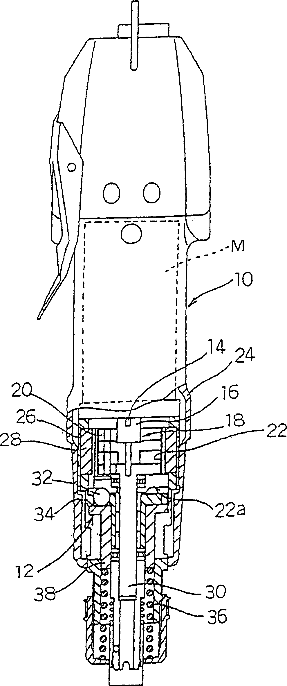
[0031] figure 1 Shown is a schematic cross-sectional view of main parts of an embodiment of an electric rotary tool implementing the torque control method of the present invention. That is, in figure 1 Among them, reference numeral 10 represents an electric rotary tool such as an electric drive such as an electric driver in which an electric motor M composed of a brushless motor or the like is built in. A pinion 16 is fixed at the front end of the output shaft 14 of the above-mentioned electric motor M, and the pinion 16 is meshed and connected by The reduction mechanism constituted by the planetary gear mechanism 18. On the outer periphery of the planetary gear mechanism 18, an internal gear 22 meshing with the planetary gear 20 is arranged.

[0032] The internal gear 22 is press-fitted a...


PUM


Abstract

A torque control system for electrically driven rotating tools capable of always properly and efficiently effecting constant-torque tightening of screws or the like and capable of easily achieving the miniaturization of the whole device and the improvement in torque control accuracy, the torque control system comprising a clutch mechanism that, when a load torque of predetermined value or above acts on a driven shaft joined to the output shaft of an electric motor, operates to cut off the engagement between the output shaft and the driven shaft, a torque setting mechanism that adjusts the engagement point for the clutch mechanism, and a torque detecting mechanism (42) for detecting the clutch operation of the clutch mechanism to effect drive stop control of the electric motor, wherein the torque detecting mechanism (42) is set so that it effects drive stop control of the electric motor simultaneously with the detecting operation thereof in a state in which the clutch operation has been completed as the cam engagement at the cam engagement portion (40a) of the clutch mechanism is completely canceled.

Description

technical field [0001] The present invention relates to a torque control method of an electric rotary tool such as an electric screwdriver, and particularly relates to a torque control method of an electric rotary tool that is controlled in such a manner that a driven shaft of the electric rotary tool receives a load torque equal to or greater than a preset value Next, this state is detected by the operation of the clutch mechanism, and the driving of the electric motor is stopped appropriately. Background technique [0002] In the prior art, as an electric rotary tool for driving an electric screwdriver or the like by an electric motor, there has been proposed and put into practical use a tool of such a structure that when tightening a screw or the like, the screwdriver bit (driver bit) is applied In the case of a strong reverse load, the state of reaching the specified torque value is detected through the clutch mechanism that operates with a preset locking torque, and the...

Claims


Application Information

Patent Timeline
Patent Type & Authority Applications(China)
IPC IPC(8): B25B23/14B25B23/147B25B23/157
CPCB25B23/147Y10T408/89B25B23/14
Inventor 户津胜行
Owner 户津胜行
Why Eureka
Try Eureka