Back light system

A technology of backlight system and light source, applied in the field of backlight system, can solve the problems of difficulty in implementation and poor uniformity of light output, and achieve the effects of increasing viewing angle, enhancing brightness and uniform light distribution

Inactive Publication Date: 2004-06-30
HONG FU JIN PRECISION IND (SHENZHEN) CO LTD +1
View PDF1 Cites 17 Cited by
  • Summary
  • Abstract
  • Description
  • Claims
  • Application Information

AI Technical Summary

Problems solved by technology

[0006] In order to overcome the defects of poor light uniformity and difficult realization of the prior art backlig

Method used


Image

  • Back light system
  • Back light system
  • Back light system

Examples


Embodiment Construction

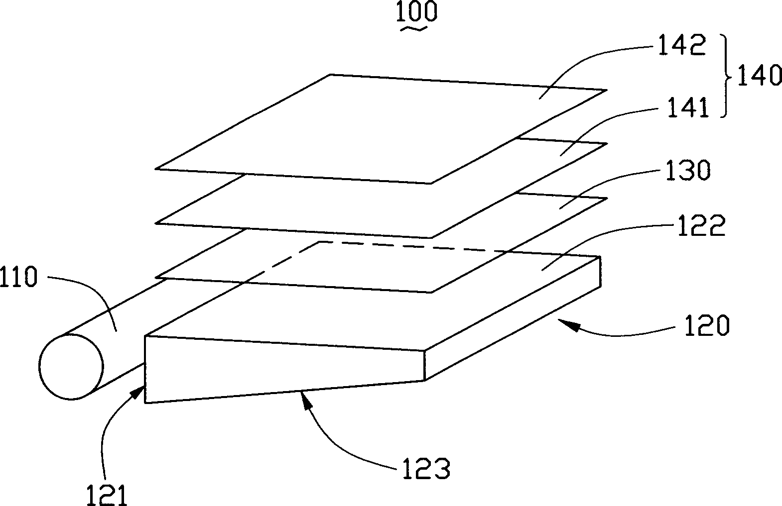
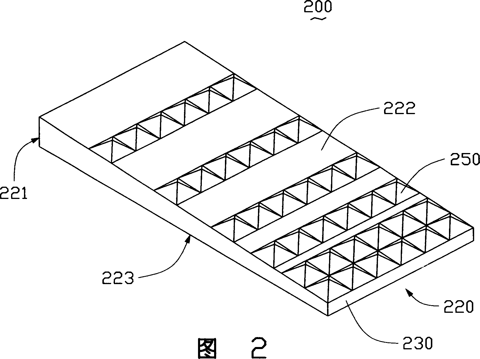
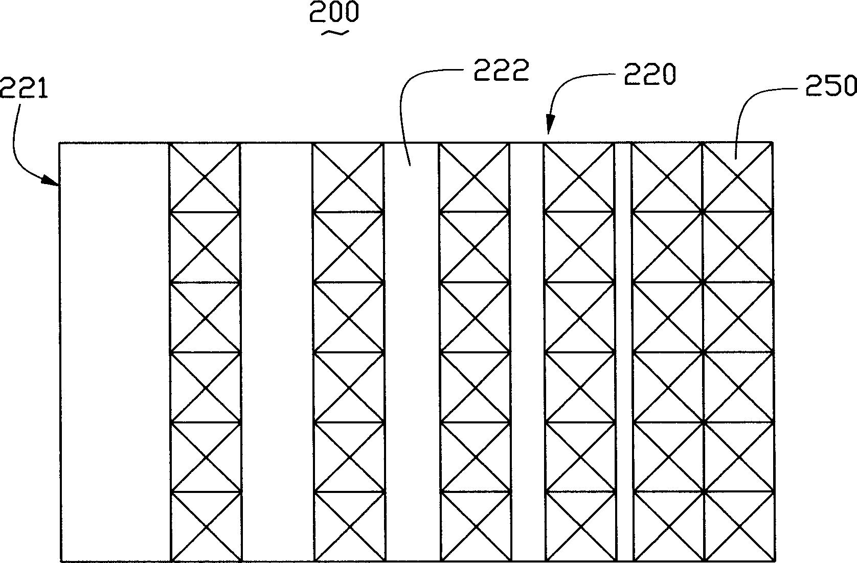
[0017] Figure 4 It is a perspective view of the first embodiment of the backlight system of the present invention. The backlight system 30 includes a light source 310 and a light guide plate 300. The light guide plate 300 is an integrally formed cuboid structure, and its material can be polyethylene, polycarbonate and the like. The light guide plate includes an incident surface 321, an exit surface 322 and a bottom surface 323, wherein the incident surface 321 receives the light beam emitted by the side light source 310 and guides the light beam into the light guide plate 300, and the bottom surface 323 guides the light beam into the light guide plate 300. The light beam is reflected and scattered to form a scattered light beam uniformly diverging in all directions. The output surface 322 guides the uniformly divergent light beam out of the light guide plate 300 and guides it to a liquid crystal display panel (not shown). The light source 310 is arranged on the light guide pl...


PUM


Abstract

The invention is a kind of light-back system, which includes a light board and a source, the light board contains an entrance face, a back surface and a exit face, the entrance face is used to receive the beam, the back surface connects with the entrance face, the exit face opposites to the back surface, which is used to guide the beam out of the light board, the source is set at one side of the entrance face. There sets many mesh spots and V type slots on the back surface, the exit surface has many even ladder type prisms structure. The prisms gather the exit lights in order to enhance the density of the exit beam of light board.

Description

【Technical field】 [0001] The invention relates to a backlight system for a liquid crystal display. 【Background technique】 [0002] At this stage, liquid crystal displays are widely used in notebook computers, desktop computers, workstations, industrial monitors, global satellite positioning systems (GPS), Personal data processing, game consoles, videophones, portable VCDs, DVDs and other portable devices. However, the liquid crystal itself does not emit light, and there must be a backlight system to provide it with the brightness required to display images. Moreover, the liquid crystal display panel is composed of a plurality of liquid crystal units, and each liquid crystal unit has the same requirement for bright light acquisition, so the backlight system must be a surface light source with uniform distribution of luminance. [0003] see figure 1 , is a prior art backlight system 100, which generally includes a light source 110, a light guide plate 120, a diffuser plate ...

Claims


Application Information

Patent Timeline
IPC IPC(8): G02B5/02G02F1/13357
Inventor 余泰成吕昌岳陈杰良
Owner HONG FU JIN PRECISION IND (SHENZHEN) CO LTD
Why Eureka
Try Eureka