Roller positioning structure of rolling mill

A configuration structure and roll technology, which is applied to the driving device, rolls, and metal rolling stands of metal rolling mills, can solve the problems of complex claw manufacturing, expensive rolls, and difficult disassembly, and achieve convenient roll replacement and roll Low risk of cracking, effect of simple contour

Inactive Publication Date: 2004-07-07
SMS MEER
View PDF0 Cites 2 Cited by
  • Summary
  • Abstract
  • Description
  • Claims
  • Application Information

AI Technical Summary

Problems solved by technology

[0005] Both of the above-mentioned solutions have certain disadvantages: When using face teeth with tie rods, the Voith-type face teeth generate strong axial forces that must additionally be absorbed
It is particularly disadvantageous that the rolls are difficult to remove because they are securely seated; the rolls have to be removed immediately after the plant has been shut down and while they are still hot
In addition, when clamping with jaws, it has been found that the bending stress quickly wears out the cylindrical bearings on the roller shafts
As the jaws are rather complicated to manufacture, the rolls, which are wearing parts, end up being expensive

Method used


Image

  • Roller positioning structure of rolling mill
  • Roller positioning structure of rolling mill

Examples


Embodiment Construction

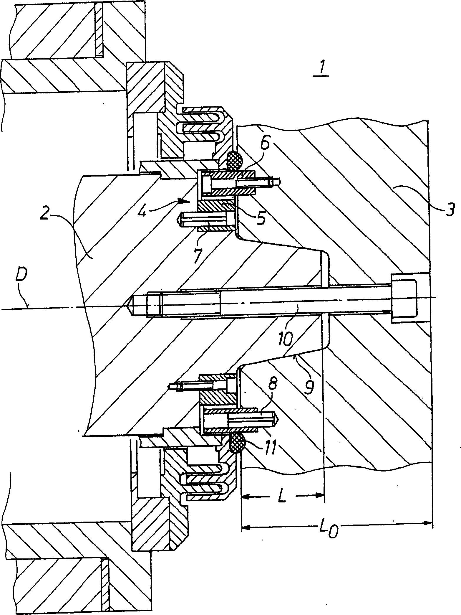
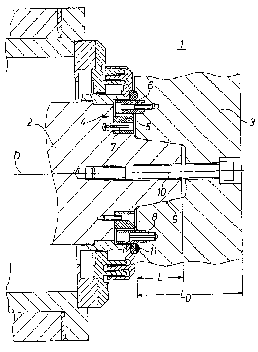
[0023] The roll arrangement 1 has a roll shaft 2 , which is rotatable about an axis D of rotation. On one axial end of the roll shaft 2 (the right end in the figure), a roll 3 is fixed. The centering of the roll 3 relative to the roll shaft 2 is effected via a conical centering mechanism 9, ie via a conical seat, which connects the two aforementioned parts to one another. The fastening of the roll 3 on the roll shaft 2 is effected by a threaded connection 10 , which here is a single screw whose axis is identical to the axis of rotation.

[0024] To ensure good centering of the roll 3 relative to the roll shaft 2 and to ensure good concentric rotation, the length L of the conical centering means 9 covers a substantial part of the entire axial extension Lo of the roll 3 . In this case, the length L of the conical centering means 9 should amount to at least 30% of the axial extent Lo of the roll 3 . This has just ensured that the bending force of roll 3 is borne by the relative...


PUM


Abstract

Roller setup (1) for a rolling mill, especially a planetary inclined rolling mill with roller (3) on roller shaft (2), which is releasably connected to roller (3), has an arrangement (4) between the roller shaft and roller (3) for positive transfer of a drive turning moment from roller shaft (2) to roller (3). Roller setup (1) for a rolling mill, especially a planetary inclined (sic) rolling mill with roller (3) on roller shaft (2), which is releasably connected to roller (3), has a arrangement (4) between the roller shaft and roller (3) for positive transfer of a drive turning moment from roller shaft (2) to roller (3). Arrangement (4) comprises a first gear (5) connected to the roller shaft and a second gear (6) connected to roller (3), and gears (5) and (6) have positive meshing.

Description

technical field [0001] The invention relates to a roll arrangement for a rolling mill, in particular a planetary skew rolling mill, which has a roll arranged on a roll shaft, which is releasably connected to the roll shaft, wherein between the roll shaft and the roll Means are provided between them for form-fitting transmission of the drive torque from the roll shaft to the roll. Background technique [0002] Especially in planetary skew rolling mills, the rolls with conical outer contours must be mounted on a roll shaft in such a way that the drive torque can be reliably transmitted from the roll shaft to the rolls, although the rolls can still be changed. [0003] It is known to use such roll shafts for the above-mentioned applications, that is, the rolls are releasably mounted on the roll shaft, wherein, in order to fix the rolls, Voith-type (Voith) face gears are usually used, which are hydraulically driven by means of a tie rod. tense. [0004] Another solution provid...

Claims


Application Information

Patent Timeline
Patent Type & Authority Applications(China)
IPC IPC(8): B21B35/14B21B13/00B21B31/08
CPCB21B13/008B21B31/08
Inventor H·J·克林根T·温特菲尔德特L·勒克霍夫
Owner SMS MEER
Why Eureka
Try Eureka