Direct downward background module
A backlight module, direct type technology, applied in the direction of optics, nonlinear optics, instruments, etc., to achieve the effect of reducing thickness
- Summary
- Abstract
- Description
- Claims
- Application Information
AI Technical Summary
Problems solved by technology
Method used
Image

Examples
Embodiment Construction
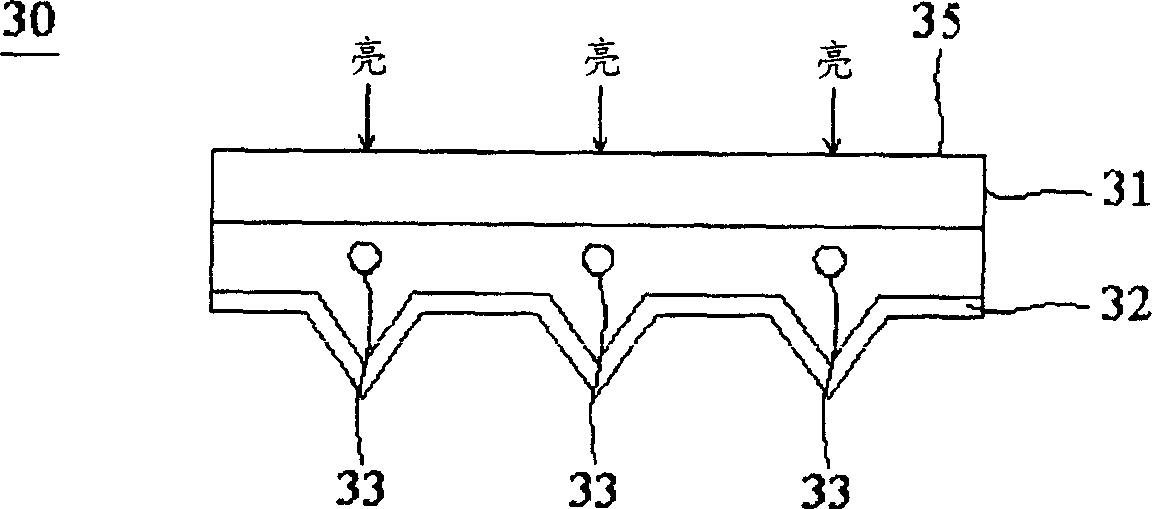
[0015] Please refer to figure 2 , which is a sectional view of the direct-lit backlight module according to the first embodiment of the present invention. In this embodiment, the direct type backlight module 100 has a light guide plate 131 , a reflector 132 and a plurality of light sources 133 , wherein the light sources 133 may be lamp tubes.
[0016] The light guide plate 131 has a light incident surface 134 and a light exit surface 135 , and the light exit surface 135 is located above the light incident surface 134 . The light incident surface 134 has a groove-shaped non-planar structure. The reflection sheet 132 is used for reflecting light. A plurality of light sources 133 are arranged between the light guide plate 131 and the reflection sheet 132; and the plurality of grooves 137 on the light guide plate 131 are arranged corresponding to the positions of the light sources 133, and each light source 133 is placed in a groove 137, which can reduce the number of backligh...
PUM
 Abstract
Description
Claims
Application Information
PatSnap Eureka turns technology decisions into work you can execute. Powered by our Innovation Knowledge Graph, it runs expert workflows across engineering, life sciences, materials and intellectual property. Get your review-ready output in minutes.


