Fluid jetting device

A fluid and ejection port technology is applied in the field of fluid ejection devices to achieve the effect of wear inhibition

Inactive Publication Date: 2004-07-07
TOTO LTD
View PDF1 Cites 11 Cited by
  • Summary
  • Abstract
  • Description
  • Claims
  • Application Information

AI Technical Summary

Problems solved by technology

Fluid ejection devices for other purposes also have the same problem in structures that rotate nozzles with fluid pressure

Method used


Image

  • Fluid jetting device
  • Fluid jetting device
  • Fluid jetting device

Examples


Embodiment Construction

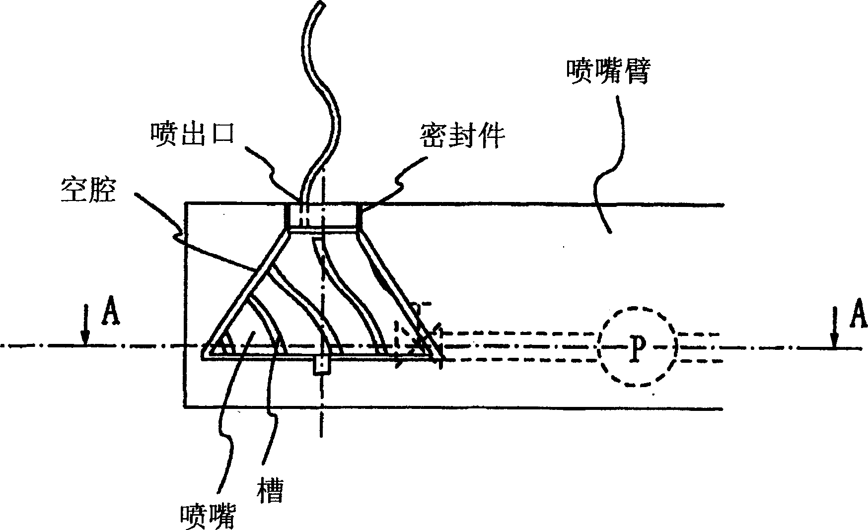
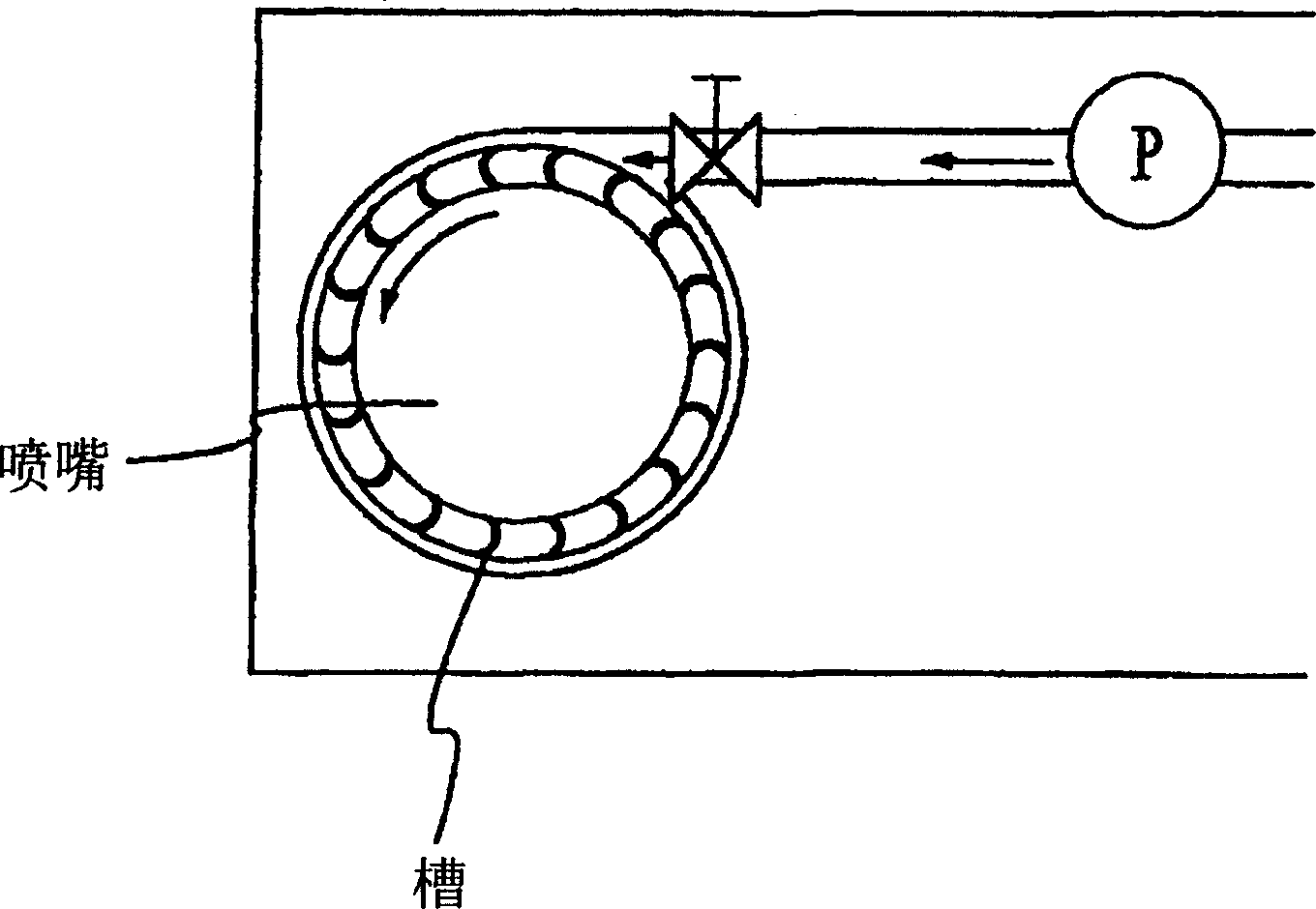
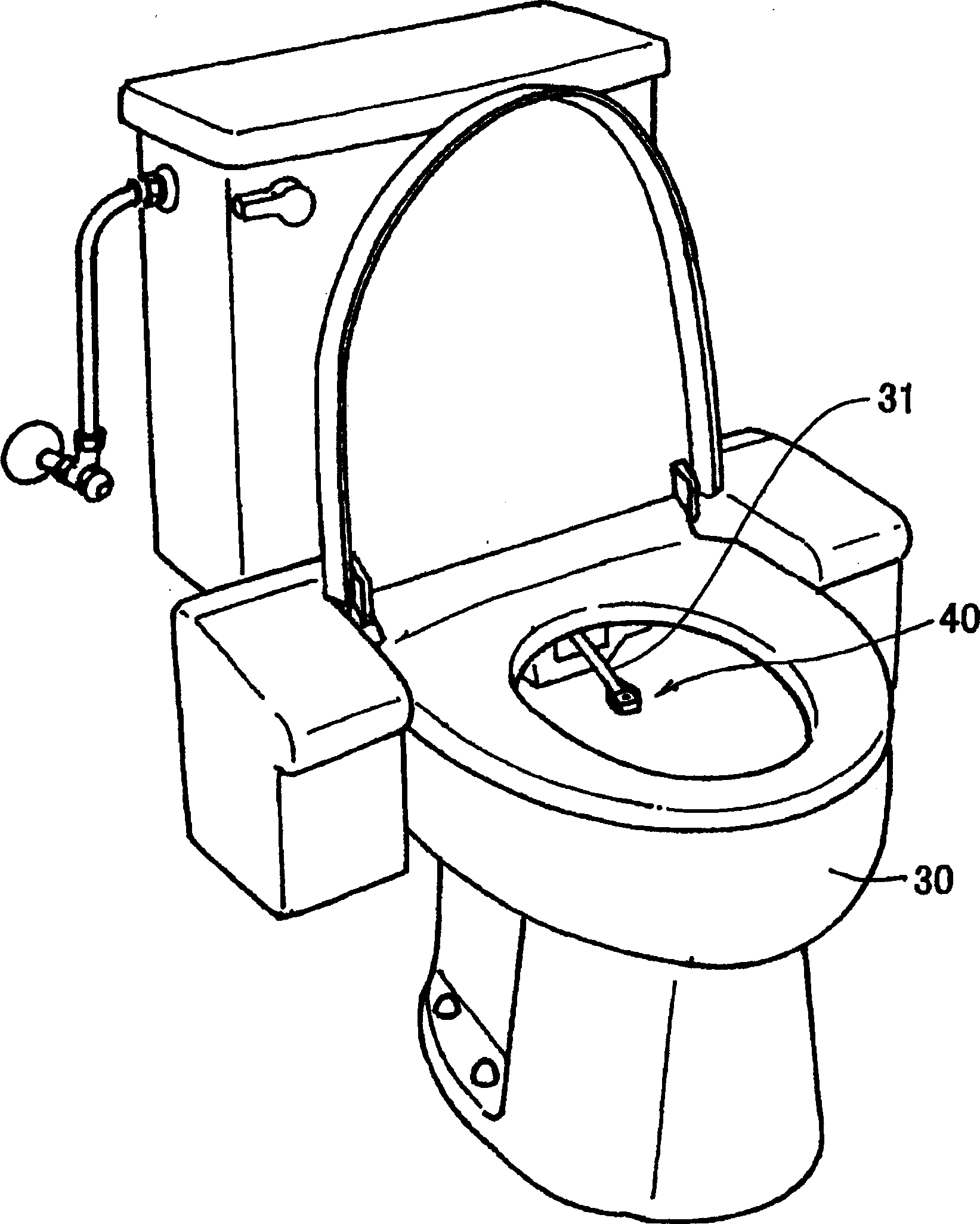
[0101] Next, embodiments of the present invention will be described based on examples. figure 2 is a schematic perspective view of the appearance of a flush toilet 30 having a flushing water spray device 40 according to an embodiment of the present invention, image 3 It is a schematic cross-sectional view in the vertical direction of the cleaning water spraying device 40 according to an embodiment of the present invention and an enlarged explanatory view of important parts thereof, Figure 4 It is a schematic cross-sectional view in the horizontal direction of this washing water spraying device 40 .

[0102] This cleansing water spraying device 40 is suitable for a human body part washing device for washing a part of a human body (such as anus, etc.) after defecation, and is provided in the nozzle arm 31 . The nozzle arm 31 is freely movable forward and backward relative to the toilet bowl, and when washing a part of the body, moves forward to a washing position as shown in ...


PUM


Abstract

A cleaning water jetting device 40 formed so as to rotate a nozzle by a fluid pressure and capable of reducing the size of the drive part of a pump for feeding fluid to a chamber and an operation cost, comprising an upper side through-hole 6A recessedly formed in edge shape provided in the ceiling of the chamber 2 and a bottomed concave part 43 formed in round hole shape provided in the bottom surface thereof, wherein the nozzle 4 is installed by inserting a reduced diameter part 7 on a nozzle tip side at the nozzle tip side into the upper side through-hole 6A and the bottom portion 44 into the concave part 43, and kept in such a state in the upper side through-hole 6A as to face a cleaning fluid jetting port 5 toward the outside of the through-hole, to be rotated, and to allow the position thereof to be changed in a nozzle axis O direction, and can be revolved around the center axis thereof in the tilted attitude relative to the center axis P of the upper side through-hole 6A.

Description

technical field [0001] The invention relates to a fluid ejection device, which comprises a cavity for containing fluid, and ejects the accommodated fluid from a fluid ejection port. Background technique [0002] As an example of this type of fluid ejection device, topical cleaning devices for cleaning a part of the human body, such as the anus, are well known. When such a local cleaning device is used, when the cleaning water is sprayed from a single fluid ejection port to a part of the human body, it is generally desirable that the water contact area of ​​the sprayed cleaning water be larger. [0003] In order to achieve such a requirement, two methods can generally be used, one method is to rotate the nozzle arm with the nozzle in a circular arc trajectory (nozzle arm rotation method), and the other is to use the nozzle arm with the nozzle inside A method of internally driving the nozzle itself (nozzle rotation method). However, with the for...

Claims


Application Information

Patent Timeline
Patent Type & Authority Applications(China)
IPC IPC(8): A47L15/18A47L15/23B05B1/14B05B3/04B05B3/06E03D9/08
CPCA47L15/4278E03D9/08A47L15/18B05B3/06A47L15/23B05B3/0463B05B1/14
Inventor 佐藤稔畠山真滨田靖夫树生能幸
Owner TOTO LTD
Why Eureka
Try Eureka