Duplexer and electronic apparatus using the same
A duplexer and circuit technology, applied in the direction of circuits, filters, electrical components, etc., can solve the problems of characteristic increase and characteristic decline
- Summary
- Abstract
- Description
- Claims
- Application Information
AI Technical Summary
Problems solved by technology
Method used
Image
Examples
no. 1 example
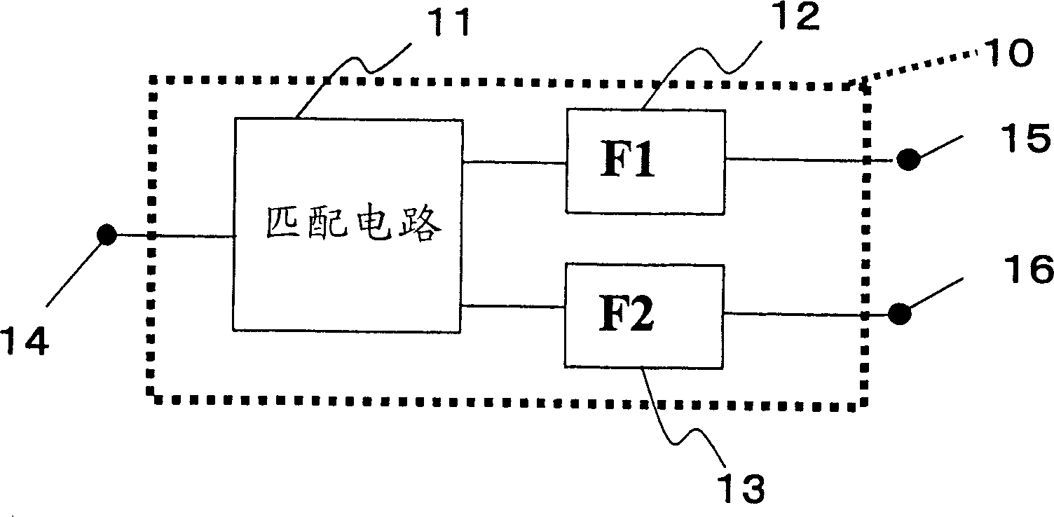
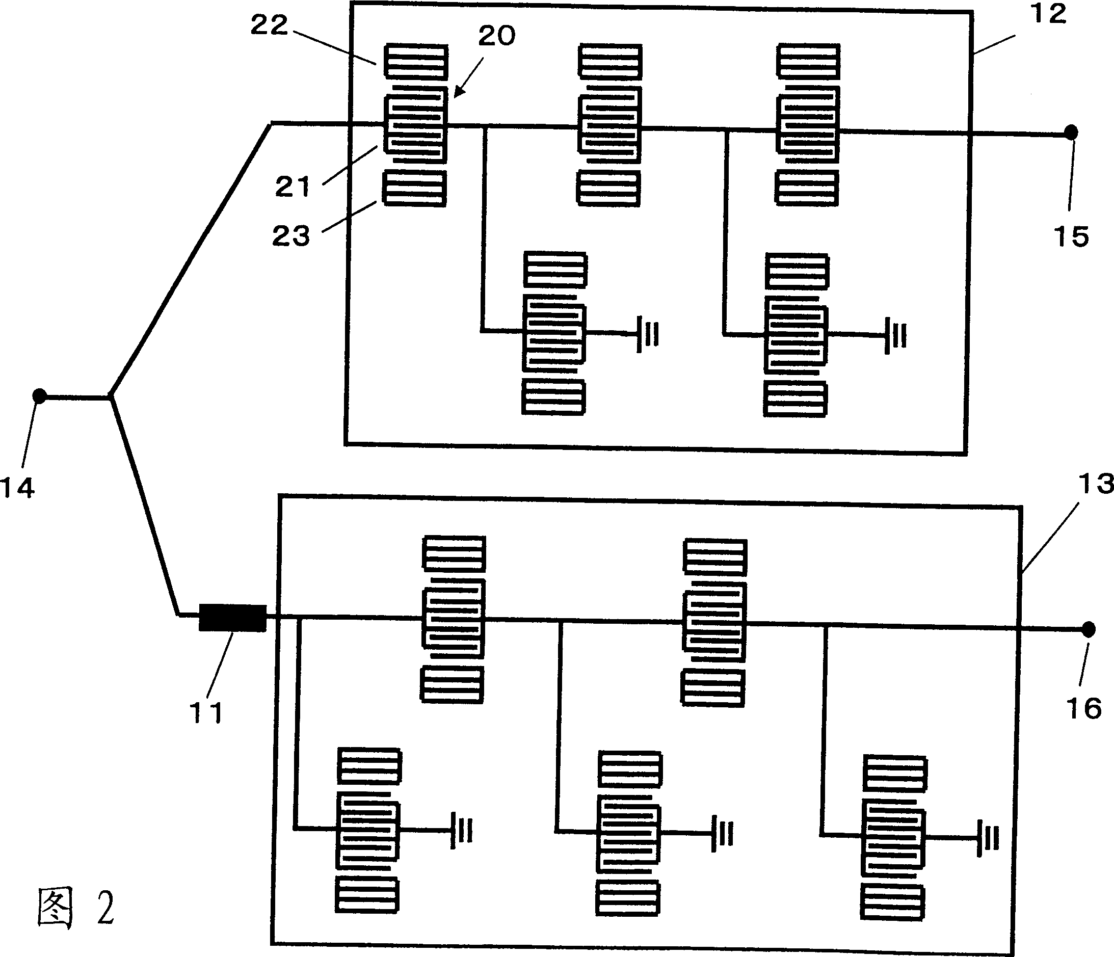
[0065] Fig. 4 shows a duplexer according to a first embodiment of the present invention. In FIG. 4 , the same elements as the aforementioned elements are denoted by the same reference numerals as the aforementioned ones. The duplexer shown in FIG. 4 includes a ladder-type surface acoustic wave filter 32 and a longitudinally coupled dual-mode surface acoustic wave filter 33 . The ladder-type surface acoustic wave filter 32 is the transmitting filter of the duplexer, and the longitudinally coupled dual-mode surface acoustic wave filter 33 is the receiving filter. These filters 32 and 33 have different band center frequencies. One end of the ladder-type surface acoustic wave filter 32 is connected to the common terminal 14 , and the other end is connected to an individual terminal (transmitting terminal) 15 . Similarly, one end of the longitudinally coupled dual-mode surface acoustic wave filter 33 is connected to the common terminal 14 via the matching circuit 11 , and the oth...
no. 2 example
[0075] Fig. 6 shows a duplexer according to a second embodiment of the present invention. In this figure, the same elements as in the first embodiment are designated by the same reference numerals as in the first embodiment. The duplexer shown in FIG. 6 is different from that of the first embodiment in that the receive filter has a balanced (differential) output through a modified connection. The duplexer shown in FIG. 6 has such a receive filter 45 . The comb electrodes of the IDT 37 of the DMS filters 34 and 35 which are grounded in FIG. 4 are connected to each other and also to the receiving terminal 46 . A balanced output is obtained via the receive terminal 46 and the further receive terminal 16 .
[0076] Figure 7A and 7B A balanced output is shown. The duplexer shown in Figure 6 is Figure 7A The duplexer 100 in. A balanced output is a signal output with the same amplitude and opposite phase, such as Figure 7B As shown in received signal 1 and received signal ...
no. 3 example
[0078] Fig. 8 shows a duplexer according to a third embodiment of the present invention. In this figure, the same elements as in the previous embodiment are indicated by the same reference numerals as in the previous embodiment. The reception filter 50 of this embodiment has a structure in which one or more DMS filters connected in parallel are cascaded. In the example shown in Figure 8, one set of two DMS filters 34 and 35 is connected to another set of two DMS filters. In FIG. 8 , the two DMS filters of the second stage connected in parallel are indicated by reference numerals 51 and 52 . The comb electrodes of the IDT 37 of the DMS filters 34 and 51 are connected to each other, and the comb electrodes of the IDT 38 of the DMS filters 34 and 51 are connected to each other, as shown in FIG. 8 . For simplicity of drawing, reference numerals 37 and 38 are assigned only to the IDT of the DMS filter 34 . The comb electrodes of the IDTs 37 and 38 of the DMS filters 35 and 52 ar...
PUM
 Abstract
Description
Claims
Application Information
 - R&D
- Intellectual Property
- Life Sciences
- Materials
- Tech Scout
- Unparalleled Data Quality
- Higher Quality Content
- 60% Fewer Hallucinations
Browse by: Latest US Patents, China's latest patents, Technical Efficacy Thesaurus, Application Domain, Technology Topic, Popular Technical Reports.
© 2025 PatSnap. All rights reserved.Legal|Privacy policy|Modern Slavery Act Transparency Statement|Sitemap|About US| Contact US: help@patsnap.com


