Backlight plate device

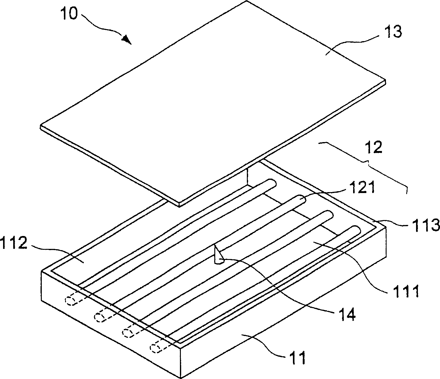
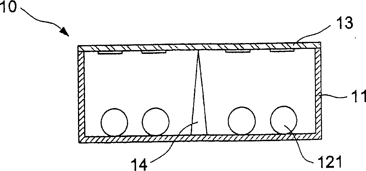
A technology for a backlight plate and a diffuser plate, which is applied in the directions of light guides, optics, and optical elements, etc., can solve problems such as the loss of illumination light source, the increase of the deformation of the diffuser plate 13 and the downward depression, and the phenomenon of bright and dark images.

Inactive Publication Date: 2004-07-28
CORETRONIC
View PDF0 Cites 8 Cited by
  • Summary
  • Abstract
  • Description
  • Claims
  • Application Information

AI Technical Summary

Problems solved by technology

[0005] Since the support column 14 directly contacts the diffuser plate 13, the contact will hinder the passage of light. In order to avoid a larger area of ​​black dot display on the diffuser plate 13, generally the support column 14 adopts a cone with a smaller cross-section at the top, so the support column 14 The top is in direct contact with the diffuser plate 13 with a sharp point, and when the size of the backlight module 10 increases or the temperature inside the frame 11 formed by the light source group 12 rises, the deformation of the diffuser plate 13 will increase and it will sag downward. At this time, the sharp point of the support column 14 is...

Method used


Image

  • Backlight plate device
  • Backlight plate device
  • Backlight plate device

Examples


no. 1 example

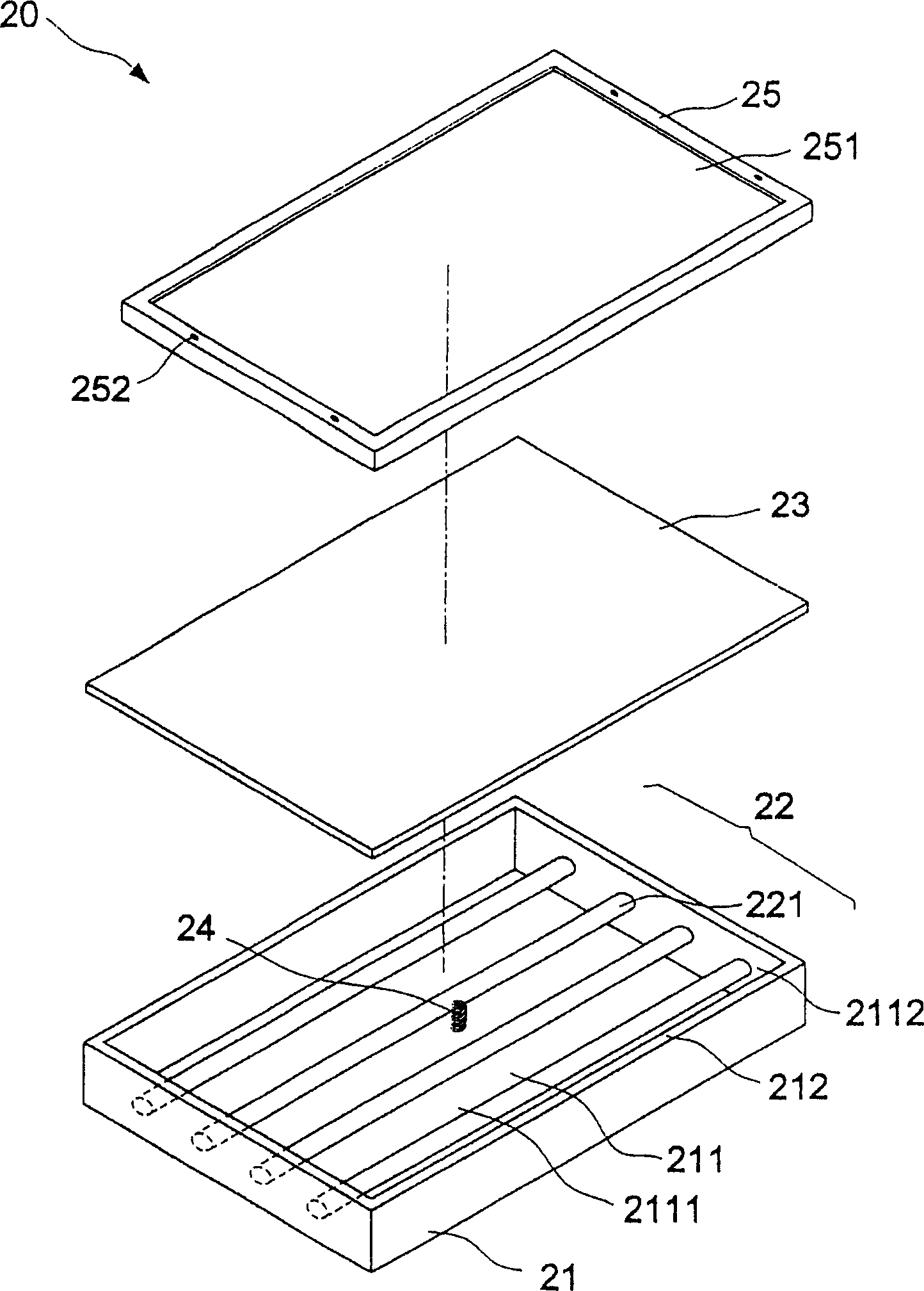
[0019] refer to image 3 , the backlight device 20 of the present invention includes a rectangular frame body 21, a light source group 22, a diffusion plate 23, at least one elastic element 24 and a cover plate 25;

[0020] Wherein the rectangular frame body 21 has a groove 211 and a top surface 212, the bottom surface 2111 and the inner side wall surface 2112 of the groove 211 are pasted with a reflective layer to reflect the light beam provided by the light source group 22 to the diffuser plate 23; the light source The group 22 is arranged in the groove 211 and includes a plurality of cold cathode fluorescent lamps 221 (CCFL). The lamps 221 are horizontally arranged in the groove 211 at an appropriate interval, and the two ends are respectively connected to the inner wall surface 2112 of the frame body 21 and fixed. The diffusion plate 23 is arranged on the top surface 212 of the rectangular frame body 21, and the surface of the diffusion plate 23 facing the lamp 221 serves ...

no. 2 example

[0025] refer to Figure 7 As shown, the present embodiment is the same as the above-mentioned first embodiment or equivalent elements are marked with the same figure number. The difference between this embodiment and the above-mentioned embodiment is that the elastic element 24 can also be a spring made of metal, and the elastic element 24 A convex body 241 can be arranged above the elastic element 24. Since the spring of the transparent or highly reflective optical material of the first embodiment is replaced, the cost can be reduced, and the convex body 241 can be made of a transparent material or a highly reflective material. For example, this embodiment adopts a tapered convex body 241 of transparent material, so that the contact surface between the convex body 241 and the diffusion plate 23 is reduced and does not block light, so as to avoid black spots appearing on the diffusion plate 23 . In addition, the convex body 241 can also be made of elastic material to prevent i...


PUM


Abstract

The present invention relates to a backlight plate device. It includes a frame body with recessed groove, a lamp source group, a diffusion plate and at least an elastic element, in which inner wall surface of the recessed groove is equipped with reflecting layer, and the lamp source group is formed from several cold-cathode fluorescence lamps which are arranged in the recessed groove, one end of the elastic element is fixed in the bottom surface of the recessed groove, and its another end is placed against the diffusion plate. It utilizes the elastic element to absorb partial diffusion plate deformation energy to reduce its deformation, said elastic element also has buffer effect so as to make the diffusion plate have optimum planeness, so that it can provide hight luminance and luminance uniformly-distributed light source for liquid crystal panel.

Description

technical field [0001] The invention relates to a liquid crystal display, in particular to a backlight plate device applied to a liquid crystal display. Background technique [0002] The backlight module (Back Light Module) is a key component of a liquid crystal display (LCD). The backlight module supplies a light source with sufficient brightness and uniformity to make the LCD panel display images. [0003] The backlight module can be roughly divided into side-light and direct-light designs according to the position of the light source. The side-light design is to install the light source of the lamp on the side of the LCD panel, and then use the light guide plate to control the direction of the beam so that the beam is projected to the A diffuser plate under the panel, thus providing a uniform beam of light for the LCD panel. Because the light source adopts a side-mounted design, it is suitable for light, thin and power-saving display devices, such as the screen of a note...

Claims


Application Information

Patent Timeline
IPC IPC(8): F21V8/00
CPCG02B6/0011
Inventor 黄炳锋
Owner CORETRONIC
Why Eureka
Try Eureka