
Thread return device of sewing machine

A sewing machine and thread device technology, which is applied to sewing machine measuring devices, sewing machine components, and thread cutting mechanisms in sewing machines, etc., can solve the problems of complicated recovery time for sewing operations, cutting sewing threads, etc.

Inactive Publication Date: 2004-08-04
JUKI CORP
View PDF0 Cites 4 Cited by
  • Summary
  • Abstract
  • Description
  • Claims
  • Application Information

AI Technical Summary

Problems solved by technology

[0011] However, in the above-mentioned conventional thread rewinding device, since the cut side end of the cut shuttle thread is cut and remains, the part on the cut end side of the shuttle thread is left inside the thread rewinding device, and it is necessary to remove it. operation, so it is very complicated and it takes time to return to the sewing operation, which is a very bad situation
[0012] In addition, even during normal sewing, the thread may be cut by the knife when the shuttle thread jumps.
[0013] The object of the present invention is to provide a thread rewinding device of a sewing machine, which can eliminate the bad situation when the thread is cut and eliminate the complicated work of restoring it.

Method used


Image

  • Thread return device of sewing machine
  • Thread return device of sewing machine
  • Thread return device of sewing machine

Examples


Embodiment Construction

[0040] (Chain Stitch Sewing Machine)

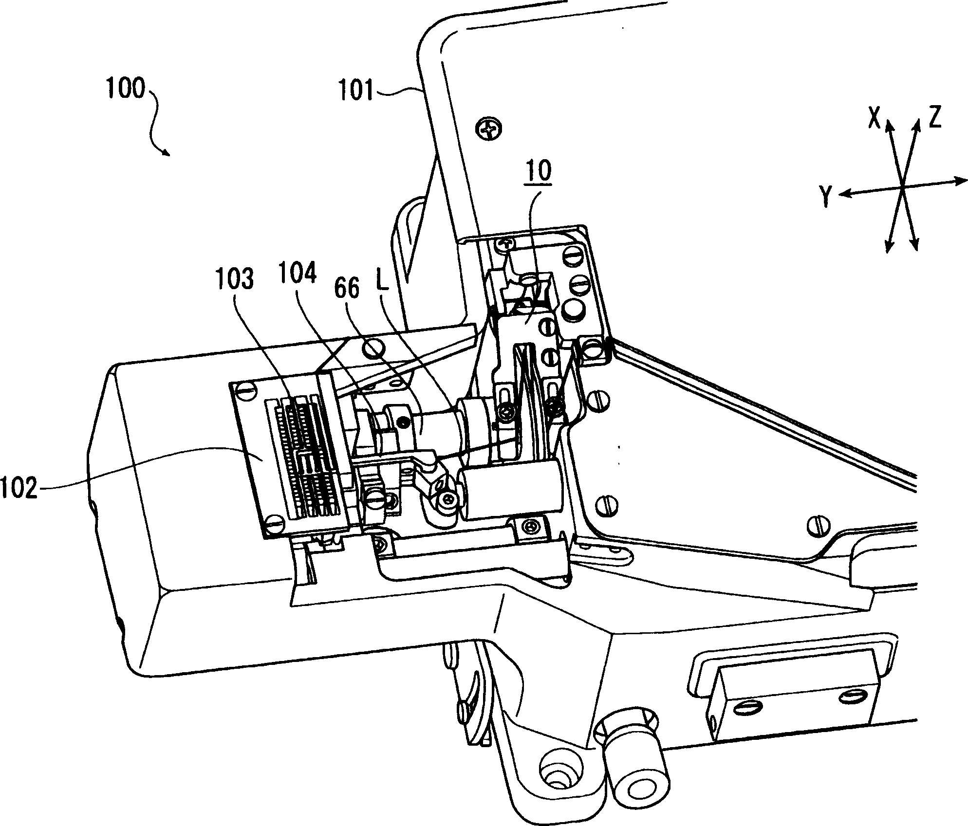
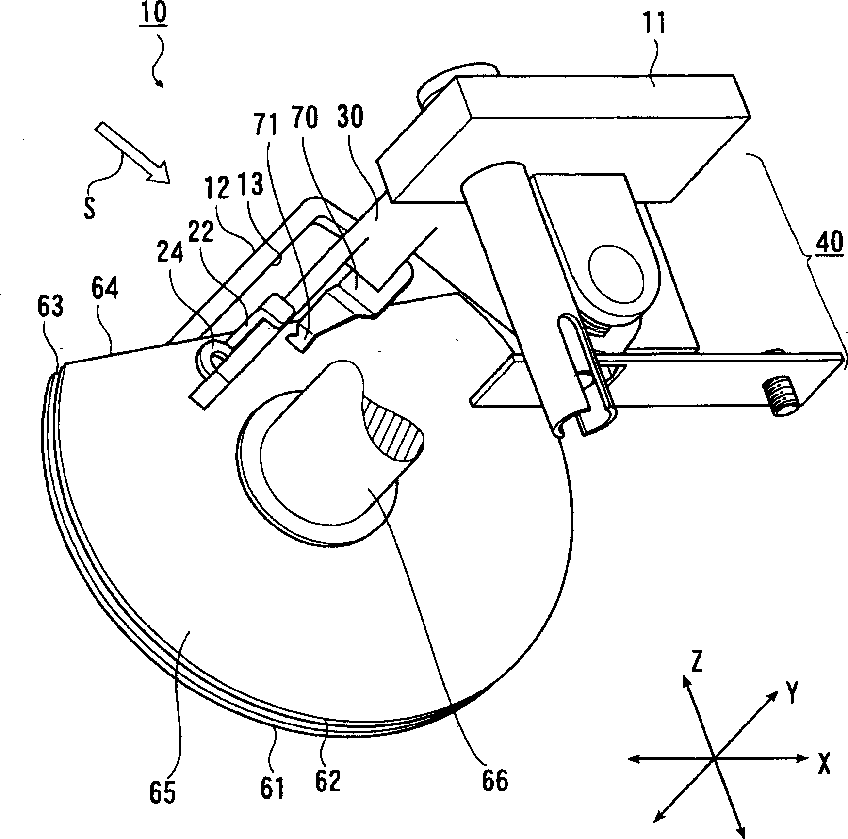
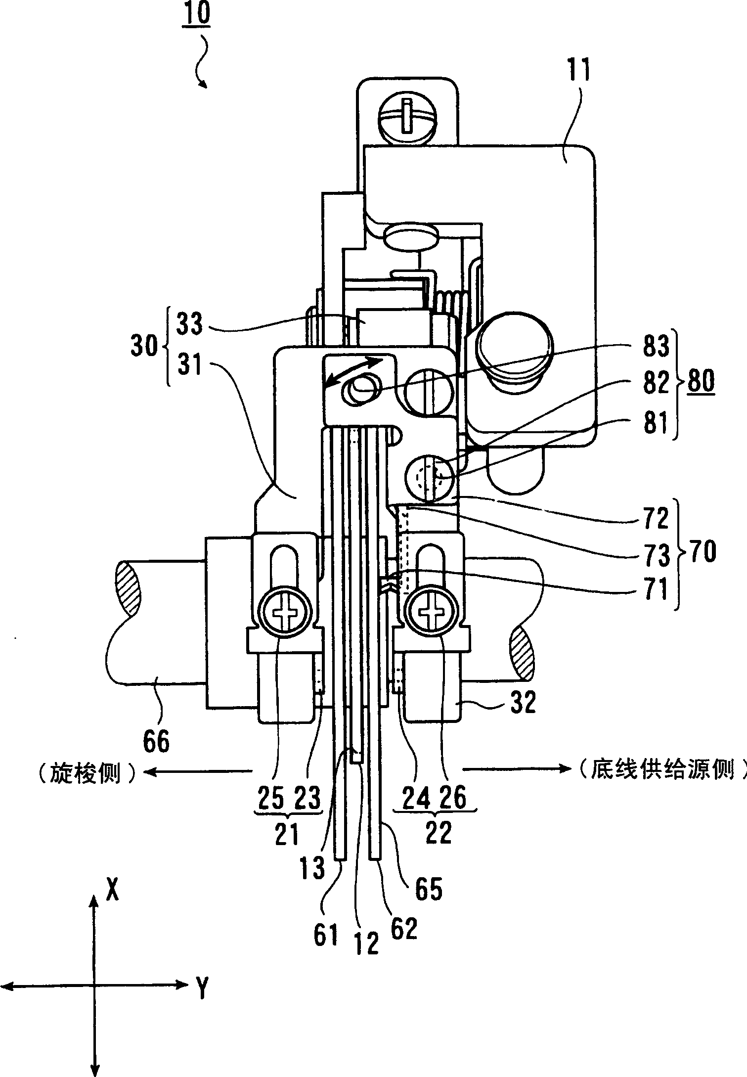
[0041] refer to Figure 1 to Figure 14 , the bobbin thread adjusting device 10 as the thread rewinding device according to the embodiment of the present invention will be described. figure 1 It is a perspective view of a state in which the bobbin thread unwinding device 10 is assembled on the sewing machine 100, figure 2 It is a perspective view of the bobbin thread unwinding device 10 viewed obliquely from below, image 3 yes figure 2 The view in the direction of the arrow S.

[0042] First, the double chain lockstitch sewing machine 100 provided with the bobbin thread unwinding device 10 will be described. Such asfigure 1 and Figure 6 As shown, the sewing machine 100 has a box-shaped bottom plate portion 101, a vertical body portion (not shown) is erected from the right end portion of the bottom plate portion 101, and extends approximately parallel to the bottom plate portion from the upper portion of the vertical body portion. ...


PUM


Abstract

To easily and quickly perform restoration work from cutting of a thread. The tread feeding device (10) of a sewing machine (100) is provided between a thread supply source and a sewing position and is provided with first and second thread insertion means (21, 22) having insertion parts (23, 24) for inserting the thread (L), a supporting body (30) for supporting the respective thread insertion means, a rotary shaft (66) rotated associated with a sewing machine motor, rotary cam plates (61, 62) fixed to the rotary shaft, arranged between the respective insertion parts and brought into slidable contact with the thread inserted between the respective insertion parts at the outer edge part, and a hook member (70) arranged such that the tip part is positioned near the plane part (65) on the thread supply source side of the rotary cam plates.

Description

technical field [0001] The invention relates to a thread rewinding device of a sewing machine which controls the amount of suture rewinding. Background technique [0002] In the past, in the bottom plate of the sewing machine, the suture (shuttle thread) should be guided from the suture supply part to the rotary hook, but the thread rewinding device for pouring the suture out from the suture supply part is all arranged between the suture supply part and the hook. In the middle of the path between the hooks. [0003] This conventional thread rewinding device has: a threading groove through which the shuttle thread is passed, two side plates facing each other formed in a state of being cut out, and a side plate supported on the same axis between the two side plates. The two rotary cam plates of the two rotary cam plates, and the release member that releases the hook thread from being captured by the rotary cam plates between the two rotary cam plates (refer to Patent Document...

Claims


Application Information

Patent Timeline
IPC IPC(8): D05B63/02D05B45/00D05B63/00D05B65/06
Inventor 礒则之藤田州司
Owner JUKI CORP
Learn More