
Elevator and traction sheave of elevator

A technology for traction ropes and sheaves, which is applied in the field of elevators and elevator traction sheaves, and can solve the problems of elevator reliability changes and cost increases

Inactive Publication Date: 2004-08-04
KONE CORP
View PDF1 Cites 9 Cited by
  • Summary
  • Abstract
  • Description
  • Claims
  • Application Information

AI Technical Summary

Problems solved by technology

The reliability of the elevator can also be altered by damage to the hoisting ropes, especially if the elevator is subjected to heavy loads, which can lead to dangerous situations, loss of coating in the traction sheave achieved by various methods of the prior art It also has the consequence that after the teeth come into contact with the wire rope, it is often necessary to replace both the traction sheave and the hoisting rope, since both are damaged
This can result in a significant increase in cost

Method used


Image

  • Elevator and traction sheave of elevator
  • Elevator and traction sheave of elevator
  • Elevator and traction sheave of elevator

Examples


Embodiment Construction

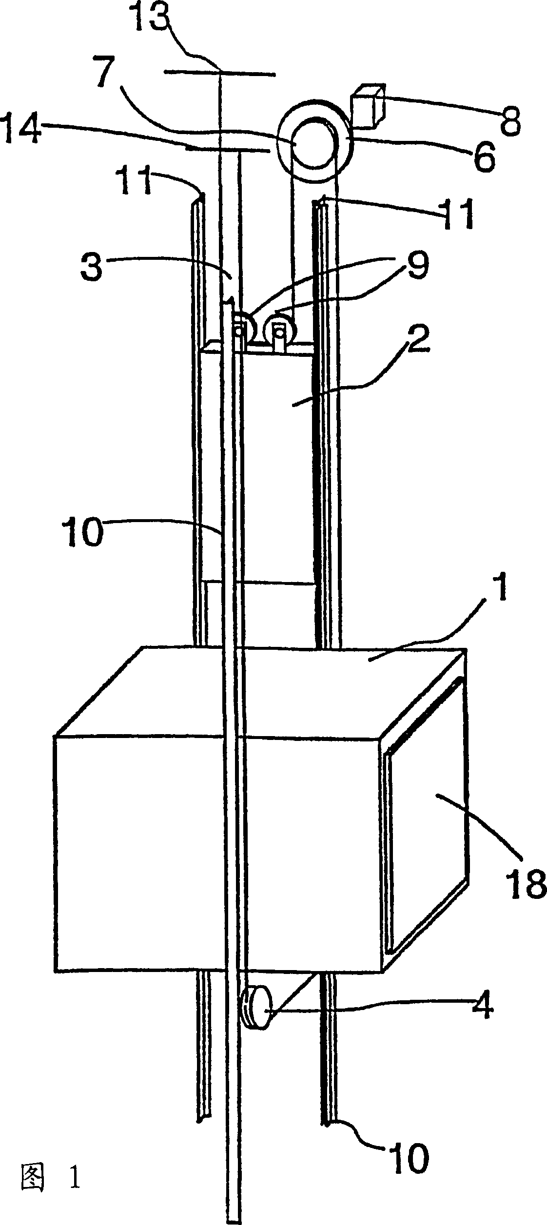
[0024] Fig. 1 is a schematic diagram of the structure of an elevator. The elevator is preferably an elevator without a machine room, and the drive machine 6 is placed in the elevator shaft, although the invention is also applicable to elevators with a machine room. The hoisting ropes 3 of the elevator travel as follows: one end of the rope set is fixed fixedly above the track of the counterweight 2 moving along the counterweight guide rails 11, on the anchor seat 13 in the upper part of the shaft, from here, each rope goes down to The counterweight is suspended and rotatably connected to the deflection pulleys 9 of the counterweight 2, and from these deflection pulleys 9, the ropes 3 go up to the traction sheave 7 of the drive machine 6, along the Each rope groove goes around the traction sheave. From the traction sheave 7 the ropes go down to the elevator car 1 moving along the guide rails 10 of the elevator car, pass under it via deflection pulleys 4 for suspending the elev...


PUM


Abstract

An elevator hoisting rope set (3) suspends a counterweight (2) and an elevator car (1). The elevator has one or more rope pulleys provided with rope grooves, one of said rope pulleys being a traction sheave (7) that moves the hoisting ropes (3). At least the traction sheave (7) has against the hoisting rope (3) a coating adhesively attached to it and increasing the coefficient of friction. At least the traction sheave (7) and the hoisting ropes (3) together form a material pair in which the hoisting ropes (3) bite into the traction sheave (7), maintaining a grip sufficient for the operation of the elevator even in an exceptional situation where the coating increasing the coefficient of friction on the surface of the traction sheave (7) is lost.

Description

technical field [0001] The invention relates to an elevator and an elevator traction sheave. Background technique [0002] Usual traction sheave elevators are based on a solution in which the steel ropes used as hoisting ropes and at the same time as suspension ropes are driven by means of metal traction sheaves, often cast iron, driven by the drive machine be driven. Movement of the hoisting ropes causes movement of the counterweight and the elevator car suspended by them. The driving force imparted to the individual hoisting ropes by the traction sheave, and the braking force by means of the traction sheave during braking, is transmitted by friction between the traction sheave and the individual ropes. [0003] The coefficient of friction between the material of the metal traction sheave used and the hoisting ropes is often insufficient to maintain a proper grip between the traction sheave and the hoisting ropes under normal conditions of elevator operation. The frictio...

Claims


Application Information

Patent Timeline
Patent Type & Authority Applications(China)
IPC IPC(8): B66B7/06B66B11/08B66B15/04F16G9/00F16H19/02F16H55/38F16H55/50
CPCB66B15/04B66B7/04
Inventor 埃斯科·奥兰科乔马·穆斯塔拉蒂
Owner KONE CORP
Learn More