
Method and equipment for carrier frequency synchronization

A carrier frequency synchronization and frequency offset technology, which is applied in the direction of synchronization devices, synchronization information channels, synchronization signal speed/phase control, etc., can solve the problems of high computational complexity of matched filters and difficult implementation of hardware equipment, and achieve structural simplification , Calculation of frequency offset simple effect

Inactive Publication Date: 2004-08-11
ALCATEL LUCENT SHANGHAI BELL CO LTD
View PDF0 Cites 5 Cited by
  • Summary
  • Abstract
  • Description
  • Claims
  • Application Information

AI Technical Summary

Problems solved by technology

For long PN sequences, the computational complexity of traditional matched filters is too high, because each sampling value requires N times of multiplication and addition, which is difficult for hardware devices to implement

Method used


Image

  • Method and equipment for carrier frequency synchronization
  • Method and equipment for carrier frequency synchronization
  • Method and equipment for carrier frequency synchronization

Examples


Embodiment Construction

[0025] The present invention will be further described in detail below in conjunction with the embodiments shown in the accompanying drawings.

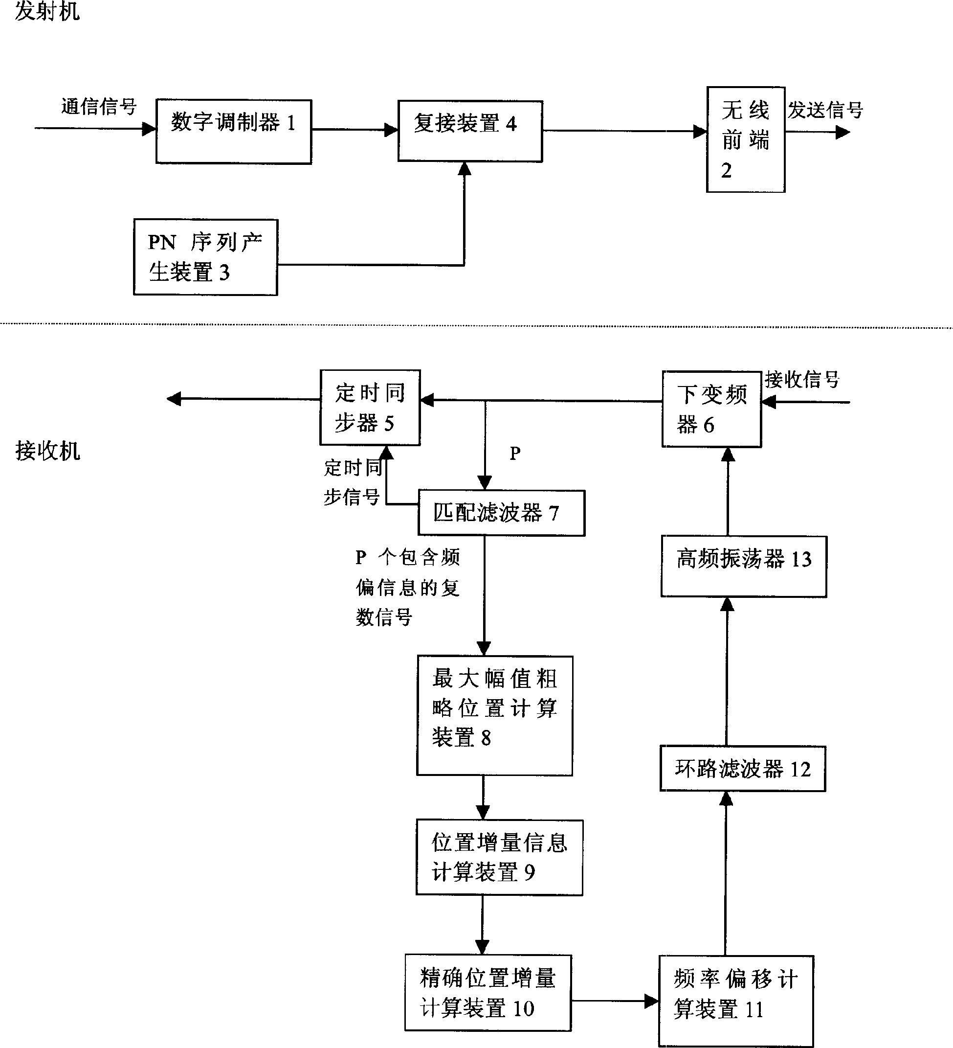
[0026] see figure 1 , figure 1 The half part on the dotted line shows a partial structural schematic diagram of a transmitter in a communication device. The transmitter of the present invention inserts the improved part of the present invention, the PN sequence generation device 3 and the multiplexing device 4, between the digital modulator 1 and the wireless front end 2, which are part of the prior art. The remaining parts of the transmitter belong to the prior art, and are not illustrated here and their descriptions are omitted.

[0027] figure 1 The lower part of the dotted line shows a partial structural principle diagram of the receiver in another communication device (ie, the communication device at the communication peer). Wherein, the timing synchronizer 5, the down converter 6, the high frequency oscillator 13 and the loo...


PUM


Abstract

The method includes following steps and devices. At sending end, specific PN sequences are inserted into every other section of digital modulated communication signals and then the signals are sent. PN sequence is C=(v X u). At receiving end, matched filtering is carried out for baseband signal containing PN sequence with frequency being converted so as to output P pieces of signals in complex number. Using likelihood function and FFT transforms the said complex signals to frequency domain, from which coarse position omega 0 of max. amplitude is found. Using Chirp-Z transform finds position increment information omega1. quadratic interpolation is carried out for omega1 to obtain position increment omega, which is exact position of max. amplitude. Frequency shift fe is calculated from formula fe=fs.(omega+omega0 - M.P / 2) / K.M.P. fe controls oscillation frequency of oscillator to reach frequency synchronism. The invention also includes receiver and transmitter for implementing the method.

Description

technical field [0001] The invention relates to a digital communication system, in particular to a carrier frequency synchronization method of the digital communication system and a transmitter and a receiver implementing the method. Background technique [0002] Traditional methods for carrier frequency synchronization include methods based on PN (pseudo noise, pseudo noise), methods based on pilot signals, methods based on prefixes, and the like. However, the PN-based method must correlate the received signal with the local PN sequence, and calculate the frequency offset with the difference method. Doing so is very complicated and not very accurate to calculate by difference. Traditional arrangements for carrier frequency synchronization have a matched filter to correlate the received signal with a locally known sequence. A traditional matched filter has an FIR structure, and the number of taps of this FIR structure is the same as the leng...

Claims


Application Information

Patent Timeline
IPC IPC(8): H04L7/04
CPCH04L7/0008H04L7/042
Inventor 黎光洁宋鹏鹏
Owner ALCATEL LUCENT SHANGHAI BELL CO LTD
Learn More