Two stroke operation engine and its two stroke operation process

A working method and engine technology, applied in the fields of engines and internal combustion engines, can solve the problems of low work efficiency, high power, and high friction loss of the mechanism.

Inactive Publication Date: 2004-08-25
CHONGQING UNIV
View PDF0 Cites 1 Cited by
  • Summary
  • Abstract
  • Description
  • Claims
  • Application Information

AI Technical Summary

Problems solved by technology

The disadvantage of this kind of working cycle is that there are many strokes, and more strokes will take up more time share. Therefore, the time for doing work is only 1/4; the work efficiency is low; more strokes lead to more friction losses of the mechanism. The inertia of the power mechanism consumes a lot of power; for this reason, we have analyzed that the

Method used


Image

  • Two stroke operation engine and its two stroke operation process
  • Two stroke operation engine and its two stroke operation process
  • Two stroke operation engine and its two stroke operation process

Examples


Embodiment Construction

[0017] The specific embodiments of the present invention will be further described below with reference to the accompanying drawings.

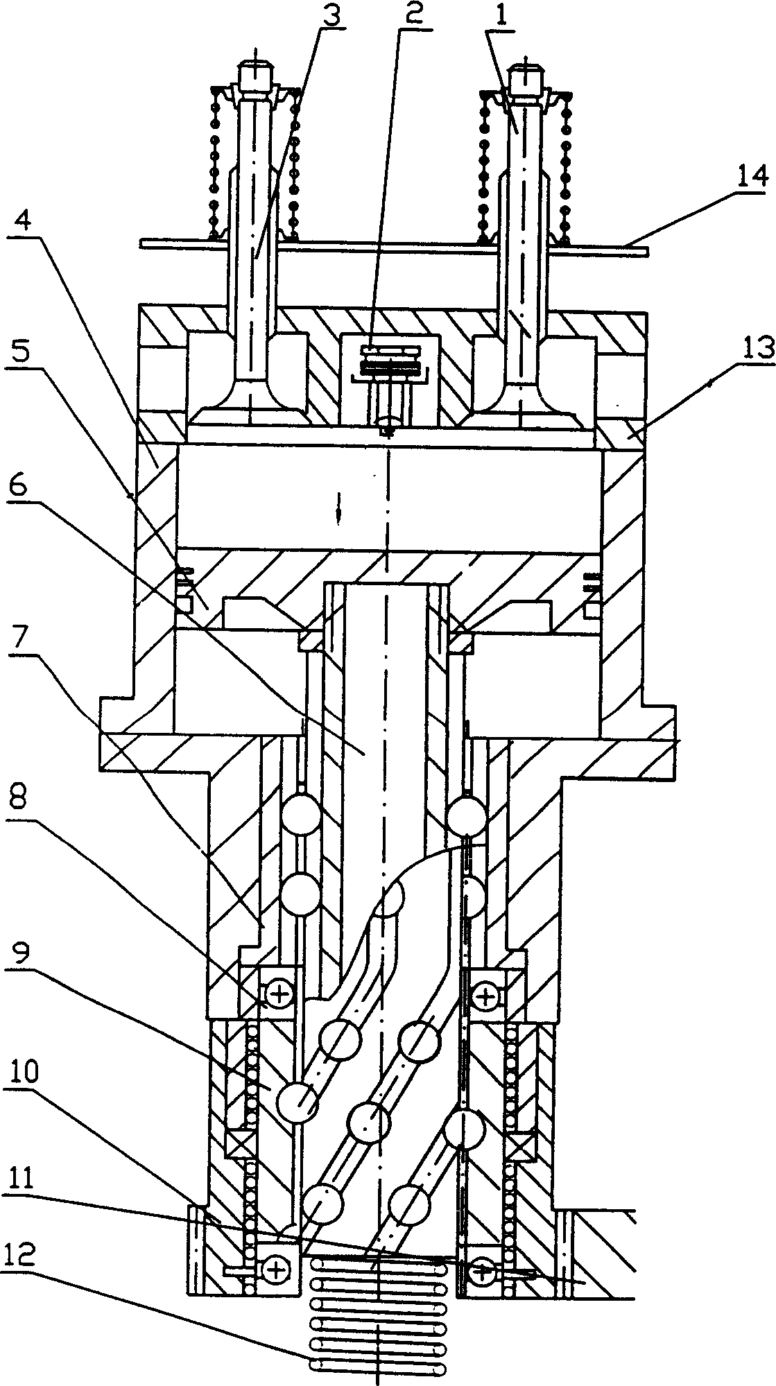
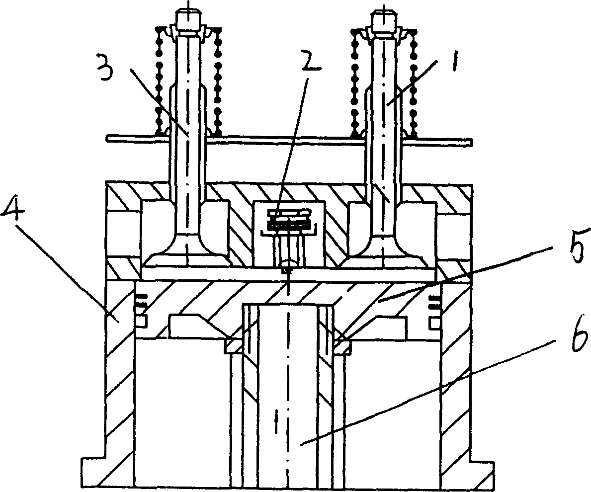
[0018] figure 1 It is a schematic diagram of the structure of the piston motion transformation mechanism.

[0019] In the figure, 1-- is the electromagnetic intake valve, 2-- is the electric spark igniter, 3-- is the electromagnetic exhaust valve, 4-- is the cylinder liner, 5-- is the piston, 6-- is the screw, 7- - is the straight spline cover, 8--thrust bearing, 9--is the spiral sleeve, 10--the electromagnetic rope clutch overcoat and gear, 11--is the output gear, and 12--is the reciprocating spring. 13---is cylinder head, and 14 is the heat insulation plate of fixing electromagnet.

[0020] The above-mentioned two-stroke engine comprises an engine cylinder liner 4, an intake valve 3 controlled by a solenoid valve, an exhaust valve 1, a conversion assembly from linear motion to rotary motion, a return spring 12, and a clutch assembly; it is...


PUM


Abstract

The two-stroke working method of two-stroke engine includes the following steps: a. the first stroke is expansion stroke, including air admission, closing admission valve, ignition, combustion, piston movement to move screw rod to drive scroll cover and make it rotate, clutch combination, clutch drives the output mechanism and makes it rotate and outputting powder; and second stroke is exhaust stroke, including: releasing clutch and back-pushing piston to the original position by reset spring. Said invented two-stroke engine includes engine body, air admission and exhaust valves controlled by electromagnetic valve, conversion component for converting linear movement into rotary movemkent, reset spring and clutch, etc.

Description

Technical field: [0001] The invention belongs to the field of internal combustion engines and engines. Background technique: [0002] Existing engines used in automobiles, trains, ships, etc. all use crank-link mechanism to complete the conversion from linear motion to rotary motion. This mechanism is not only a component for converting power, but also a work cycle control component. The movement is fixed as the first stroke-work, the second stroke-exhaust, the third stroke-suction, and the fourth stroke-compress air, which has become a classic of piston movement. The disadvantage of this kind of working cycle is that there are many strokes, and more strokes will take up more time share. Therefore, the time for doing work is only 1 / 4; the work efficiency is low; more strokes lead to more friction losses of the mechanism. The power consumed by the inertia of the power mechanism is large; for this reason, we have analyzed that the third stroke and the fourth stroke can be omi...

Claims


Application Information

Patent Timeline
IPC IPC(8): F02B75/02
Inventor 梁锡昌
Owner CHONGQING UNIV
Why Eureka
Try Eureka