
Paper feeding device, image reading device and image forming device

A technology of an image reading device and a feeding device, which is applied to the electric recording process applying the charge pattern, the equipment of the electric recording process applying the charge pattern, the supply of objects, etc. Sensors, difficulty in adding files, etc., to prevent contamination

Inactive Publication Date: 2004-08-25
SHARP KK
View PDF3 Cites 11 Cited by
  • Summary
  • Abstract
  • Description
  • Claims
  • Application Information

AI Technical Summary

Problems solved by technology

[0003] However, for the above-mentioned device capable of setting many sheets, when the sheet containing device is in its lowest stationary standby position, the capacity of the sheets is increased, but after receiving a reading start signal sent by key operation or other similar operations, It takes time to raise the paper conveying device so that the paper accommodating device is in a state of feeding documents to the conveying path
Therefore, there is a problem: the total read time to read the file increases
However, according to this prior art, although it is possible to draw out the document or align it, there is a problem that it is sometimes difficult to add the document and a sensor is required

Method used


Image

  • Paper feeding device, image reading device and image forming device
  • Paper feeding device, image reading device and image forming device
  • Paper feeding device, image reading device and image forming device

Examples


no. 1 example

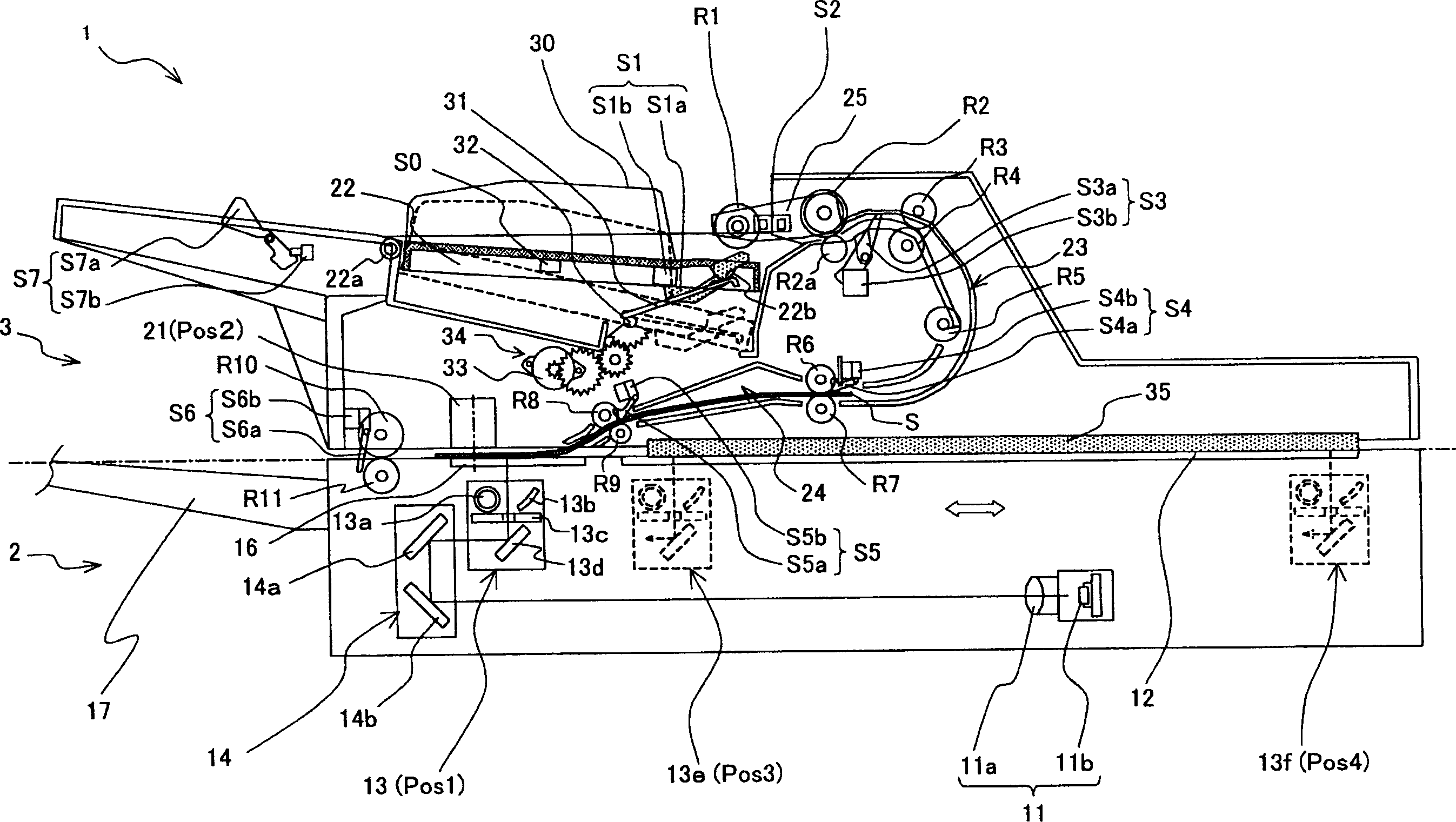
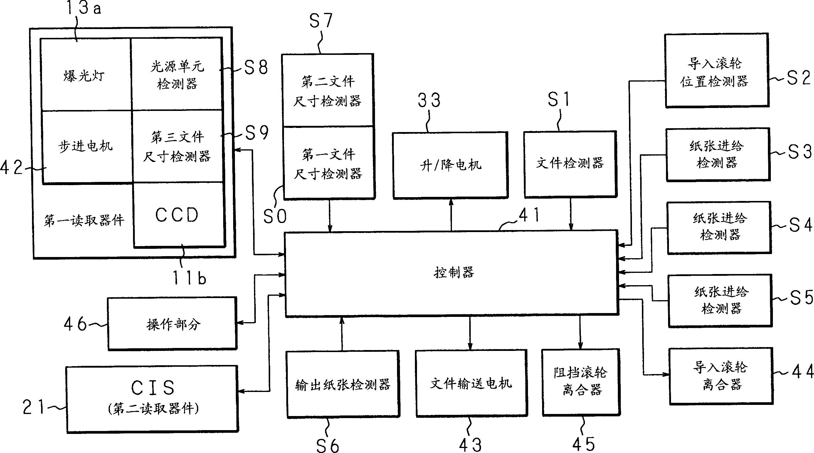
[0035] figure 1 is a vertical sectional view showing the overall structure of the image reading device of the first embodiment. exist figure 1 Among them, an image reading device 1 roughly includes an optical system 2 and an ADF (Automatic Document Feeder) 3 provided on the optical system 2 . This image reading device is used as a scanning device capable of reading images formed on both sides of a document.

[0036] The optical system 2 includes: a CCD (Charge Coupled Device) reading unit 11 as a first reading device; a light source unit 13 and a mirror unit 14 . An image of a document placed on a document shelf 12 made of flat glass and supported by a plane is read by a CCD reading unit 11 disposed at a predetermined position using a light source unit 13 and a mirror unit 14 . The CCD reading unit 11 includes an imaging lens 11a and a CCD 11b and the reflected light from the document through the imaging lens 11a is focused on the CCD 11b through various parts which will be...

no. 2 example

[0124] Although the paper feeding device according to the present invention is used on an image reading device in the first embodiment, it can also be used on an image forming device such as a printer, a complicated machine having a scanning function, a printer function and a facsimile function superior. According to this embodiment, a description will be given of a case where an image forming apparatus is an embodiment of the present invention.

[0125] Figure 10 is a vertical sectional view showing a schematic structure of the image forming apparatus of this embodiment. The image forming apparatus 100 of this embodiment includes: the above-mentioned image reading apparatus 1; an image forming unit 210, which is used to form an image on paper; processing; and a paper feeding unit 270 for feeding and conveying paper to said image forming unit 210. An image forming unit 210 is provided under the image reading device 1 . A post-processing unit 260 and a paper feeding unit 2...


PUM


Abstract

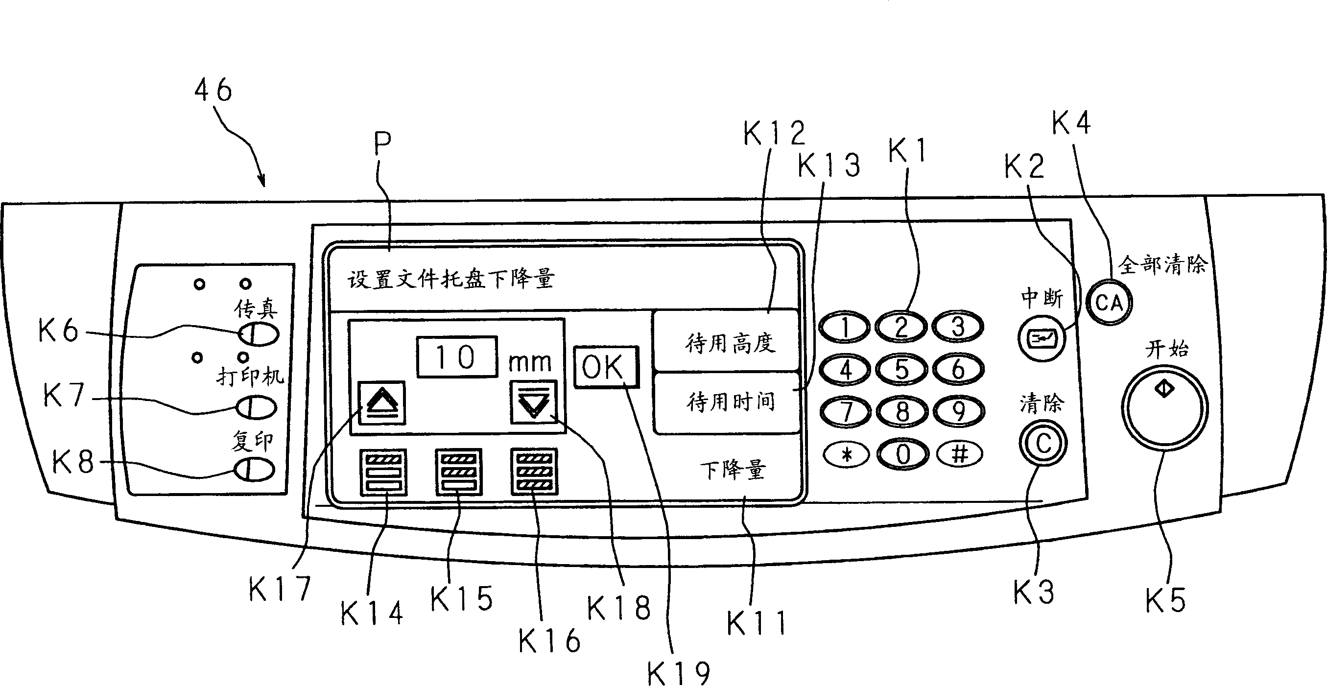
In a standby state wherein a document is set in a document tray and can be supplied when needed, when a start signal is not inputted (S21: NO), a controller determines whether a document regulating plate has been operated or not based on a detection output of a document size detector for detecting a position of the document regulating plate (S31), and when the document regulating plate was operated (S31: YES), the controller lowers the document tray by a predetermined amount and stops it (S32). A lowered amount of the document tray can be arbitrarily set by a user through an operator control panel. With a sheet feeding apparatus, an image reading apparatus and an image forming apparatus constituted as described above, even in a state in which the document is set in the document tray, the set state can be easily canceled by operating the document regulating plate.

Description

technical field [0001] The present invention relates to a paper feeding device which is mounted on an image reading device such as a copying machine and a scanner, or is mounted on an image forming device such as a printer and a facsimile, for sequentially taking out a stack of paper such as a paper containing device. The paper sheets of the placed documents are fed and conveyed to the conveying channel. The present invention also relates to an image reading device and an image forming device provided with the paper feeding device. Background technique [0002] At present, there is a device that can automatically take out and convey paper sheets from a document one by one, and then sequentially read document images is mounted on an image forming device or the like, so that images can be efficiently read and formed based on the Read an image of an image. At the same time, with the development of digital technology, the speed of reading images from documents, the speed of co...

Claims


Application Information

Patent Timeline
Patent Type & Authority Applications(China)
IPC IPC(8): G03G15/00B65H1/00B65H1/08B65H1/14B65H1/18B65H7/08
CPCB65H2553/21B65H2511/10B65H2701/1315B65H2553/25B65H1/18B65H2513/53B65H2511/20B65H2403/411B65H7/08B65H1/08B65H2220/01B65H2513/52B65H2220/02B65H2220/11B65H2220/03
Inventor 长尾裕之西田孝中村一夫高田聪一
Owner SHARP KK
Learn More