Microfluidic configuration for dosing liquids

A technology of micro-liquid and flow-cutting devices, which can be used in measuring devices, enzymology/microbiology devices, sampling devices, etc., and can solve problems such as pressure shocks

Active Publication Date: 2004-09-01
BOEHRINGER INGELHEIM MICROPARTS
View PDF1 Cites 11 Cited by
  • Summary
  • Abstract
  • Description
  • Claims
  • Application Information

AI Technical Summary

Problems solved by technology

[0003] A disadvantage of hitherto microfluidic devices for dosing and separation by means of the gas phase is that a pressure must be provided in order to generate underpressure or overpressure (suction or blow-off) to separate the first volume from the second volume. generating means, by means of which the necessary pressure shocks are produced

Method used


Image

  • Microfluidic configuration for dosing liquids
  • Microfluidic configuration for dosing liquids
  • Microfluidic configuration for dosing liquids

Examples


Embodiment Construction

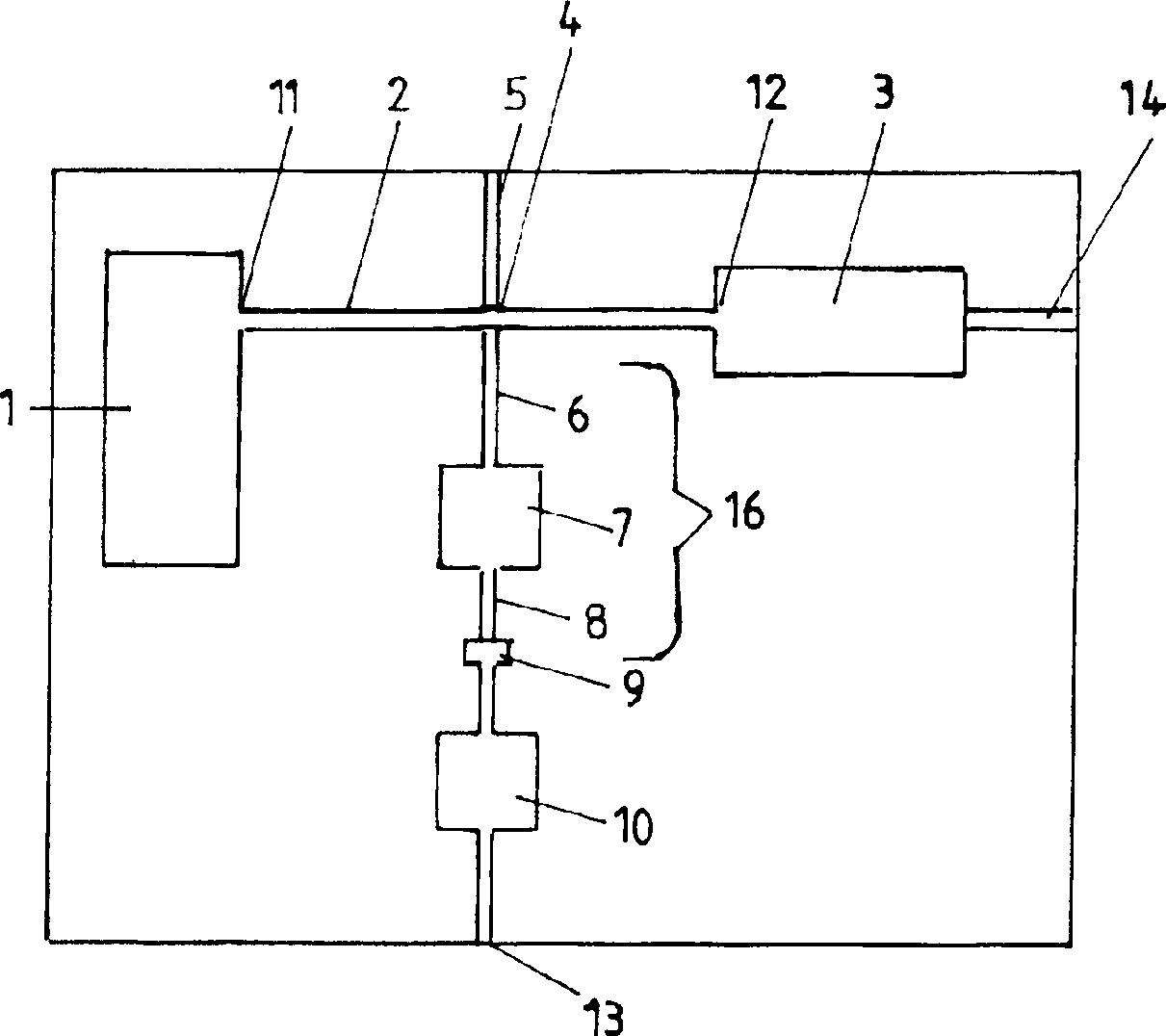
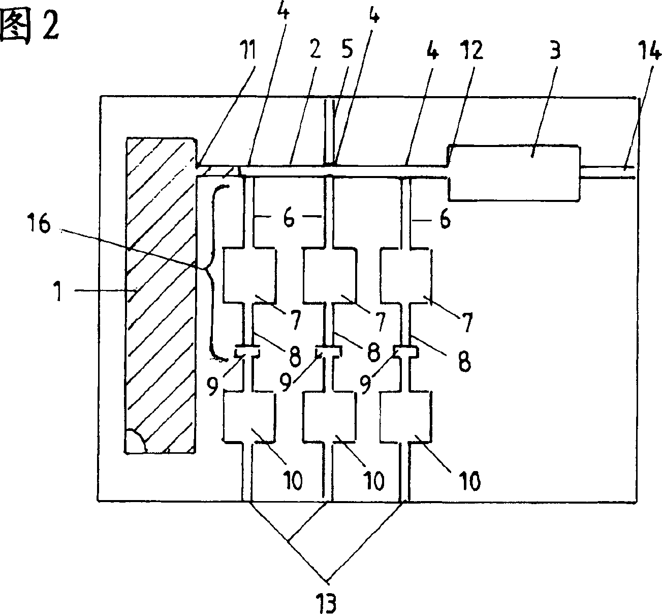
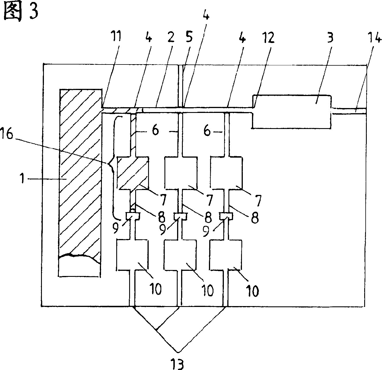
[0023] Figure 1-8c The embodiments of microfluidic devices shown in can be part of a larger general arrangement. For example, they can be provided for the same purpose or for a different purpose with further microfluidic devices, in particular microtiter plates, placed on eg plastic or silicon sample holders.

[0024] Now rely on the basis Figures 8a-8c The simplified embodiment of the present invention illustrates the principles according to the invention. in accordance with Figures 8a-8c The microfluidic device has a first channel 2 with an inlet and an outlet 12. At the tap point 4 of the second channel 2 between the inlet 11 and the outlet 12 , a second channel 16 is tapped off from the first channel 2 . This second channel 16 has a greater capillary force at the tap point 4 than the first channel 2 . Furthermore, the second channel 16 has a precisely defined volume. The liquid entering the first channel 2 through the inlet 11 is transported to the tap point 4 due...


PUM


Abstract

The invention relates to a microfluidic arrangement for metering one or more first metered amounts of liquid (A) and for separating the latter from a second amount of liquid (B), having the following features: the arrangement has a first channel and one or more one or more second channels; the first channel has one inlet and one outlet; in the area of the outlet the arrangement has a capillarity, which is greater than or equal to the capillarity in the area of the inlet; the one or more second channels branch off from the first channel at one or more branch points; the one or more second channels have a greater capillarity than the first channel at the branch points; and the one or more second channels have a predetermined volume. In the arrangement as depicted in the invention a liquid is transported in the first channel from the inlet to the outlet. At the branch points one portion of the liquid at a time enters the one or more second channels and fills them completely with the first metered amounts of liquid (A). The portion of the liquid remaining after the last branch point in the first channel emerges as the second amount of liquid via the outlet from the first channel. The amounts of liquid (A) metered in the one or more second channels are separated from the remaining amount of liquid (B) by a gas, which is located in the first channel after filling all second channels.

Description

technical field [0001] The present invention relates to a microfluidic device for dispensing and separating one or more first dosed fluid volumes from a second fluid volume. Background technique [0002] Various such microfluidic devices are disclosed in the prior art. Such microfluidic devices are used, for example, for dispensing doses and injecting liquids for wet chemical, biochemical and diagnostic analyses. In this respect, the volume element is filled with a defined first fluid volume. This determined liquid volume is separated from the remaining second liquid volume. Currently, the remaining liquid volume is generally separated from the dispensed volume by means of mechanical elements or a gas phase. The gas phase can be maintained by sucking off the remaining liquid volume. It is likewise possible to "blow off" the remaining liquid quantity from the liquid quantity of the dispensed dose by means of a pressure shock. [0003] A disadvantage of hitherto microflui...

Claims


Application Information

Patent Timeline
Patent Type & Authority Applications(China)
IPC IPC(8): B01J4/00B01L3/00G01F11/28G01N1/00G01N1/10G01N37/00
CPCB01L2200/0605G01F11/28B01L3/502784B01L2300/0861B01L2400/0688B01L2400/0406B01L3/502738B01L3/5027B01L2400/0487Y10T436/2575Y10T436/25375
Inventor 拉尔夫·彼得斯格特·布兰肯施泰因德克·奥斯特洛
Owner BOEHRINGER INGELHEIM MICROPARTS
Why Eureka
Try Eureka