Supercharge Your Innovation With Domain-Expert AI Agents!

Stencil printer

A printing machine and stencil technology, which is applied to stencil printing equipment, printing, office printing equipment, etc., can solve the problems of increasing the cost of stencil printing machines

Inactive Publication Date: 2004-09-01
RICOH KK
View PDF4 Cites 0 Cited by
  • Summary
  • Abstract
  • Description
  • Claims
  • Application Information

AI Technical Summary

Problems solved by technology

However, this configuration increases the cost of the stencil printing machine, since specific moving devices must be assigned to each of the stretching member and the movable negative plate guide

Method used


Image

  • Stencil printer
  • Stencil printer
  • Stencil printer

Examples


Embodiment Construction

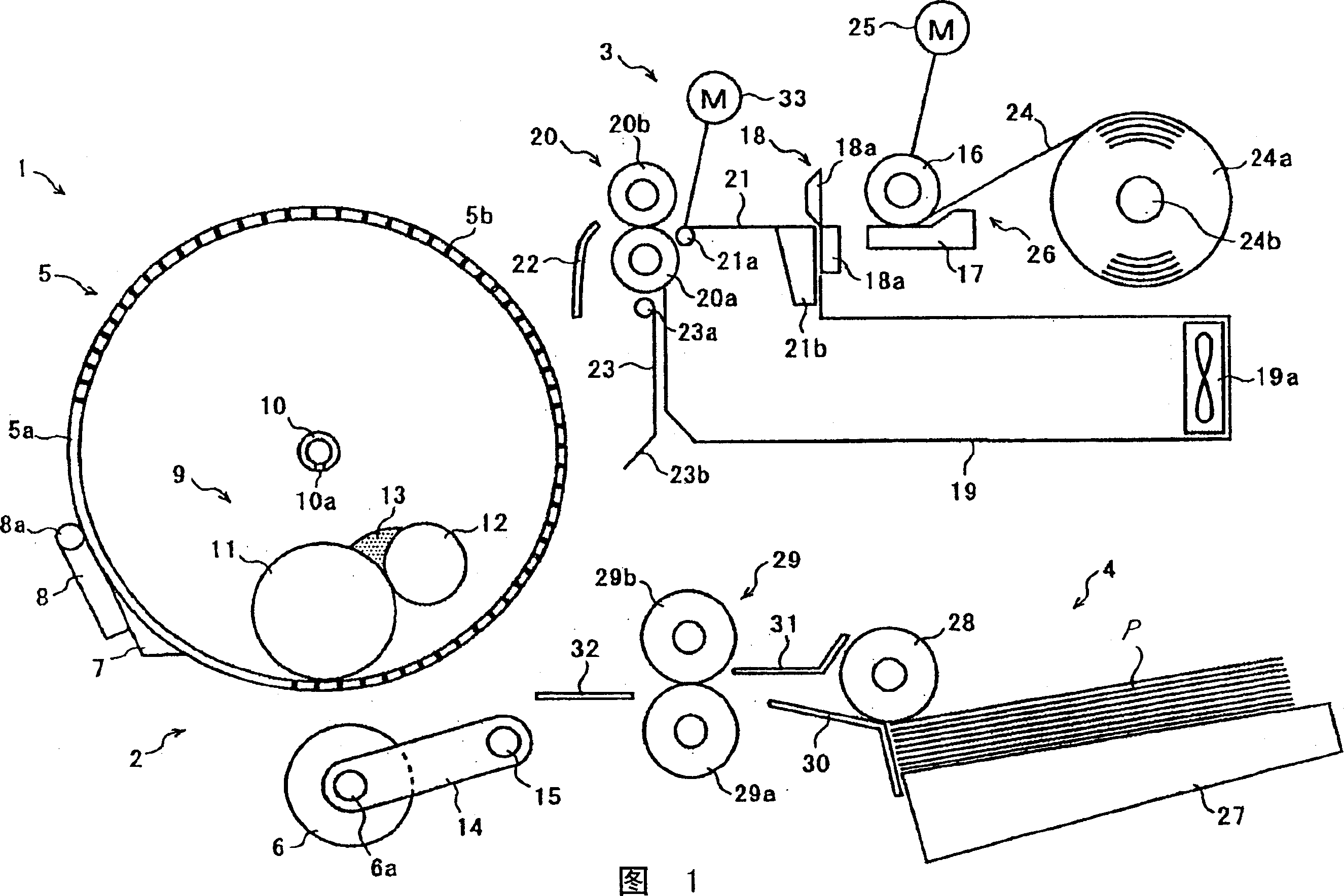
[0022] Referring to Figure 1 of the drawings, a stencil printing machine embodying the invention is shown and generally designated by the reference numeral 1 . As shown, the stencil printing machine 1 generally includes a printing section 2 , a master making and conveying section 3 , and a sheet feeding section 4 .

[0023] The printing section 2 comprises a printing drum 5 and a pressure roller 6 . The printing drum 5 is positioned at the approximate center of an unillustrated printing machine body, and is caused to rotate clockwise by an unillustrated printing drum driving device, as shown in FIG. 1 . The pressing roller 6 is movable toward and away from the printing drum 5 , and presses the sheet or recording medium P supplied from the sheet feeding section 4 against the printing drum 5 while moving toward the printing drum 5 .

[0024] The printing drum 5 has a pair of flanges at its axially opposite ends, although not specifically shown. The porous support 5a is fixed o...


PUM


Abstract

A stencil printer of the present invention includes a print drum for wrapping a master therearound, a master making and conveying section for perforating a stencil paid out from a stencil roll while conveying it to thereby produce the master, a master stocking section for stocking the master being conveyed by the master making and conveying section, and a roller pair for conveying the master out of the master stocking section. A movable master guide selectively guides the stencil paid out from the stencil roll to the master stocking section or the roller pair. A stretching member adjoins the print drum and is movable between a contact position where it contacts the stencil present on the print drum to thereby exert a stretching force on the master and a released position where the former is released from the latter. The stretching member and movable master guide are interlocked to each other.

Description

technical field [0001] The present invention relates to a stencil printing machine for printing an image on a sheet or recording medium by winding a master or perforated stencil on a printing drum. More particularly, the present invention relates to a stencil printing machine of this type that includes a stretching member configured to exert a stretching force on a master and a master storage device for storing the master. Background technique [0002] A stencil used in a stencil printing machine has a laminated structure comprising a thermoplastic resin film about 2-8 [mu]m thick and a porous support adhered to each other. The porous support is formed from Japanese paper or synthetic fibers or a combination thereof. A thermal head or similar heating unit uses heat to selectively penetrate or cut a thermoplastic resin film according to image data, thereby making a master. After the master has been wrapped around the printing drum, a press roller or similar pressurizing mem...

Claims


Application Information

Patent Timeline
Patent Type & Authority Applications(China)
IPC IPC(8): B41L13/14
CPCB41L13/14
Inventor 森富也高桥正纪小林一喜椿健悟
Owner RICOH KK
Features
  • R&D
  • Intellectual Property
  • Life Sciences
  • Materials
  • Tech Scout
  • Unparalleled Data Quality
  • Higher Quality Content
  • 60% Fewer Hallucinations
Learn More