Reduction gear box of electric machine

A reduction gear box and reduction box technology, applied in the direction of gear transmission, belt/chain/gear, electrical components, etc., can solve the problems of high manufacturing difficulty, affecting the smooth rotation of gears, complex structure, etc., and achieve manufacturing and assembly Simplicity and convenience, improved sealing performance, and simplified overall machine structure

Inactive Publication Date: 2004-09-01
ZHEJIANG LINIX MOTOR
View PDF0 Cites 6 Cited by
  • Summary
  • Abstract
  • Description
  • Claims
  • Application Information

AI Technical Summary

Problems solved by technology

The motor gearbox with this structure has many parts and a relatively complicated structure, which not only has high manufacturing cost, complicated manufacturing process, and high manufacturing difficulty, but also is not conducive to controlling the sealing of the motor.
[0003] Its other defect is that the end cover of the reduction box punches out the accommodating hole for the bearing of the reduction mechanism by punching. The gears and drive shafts cannot be meshed and assembled together, which affects the smooth rotation of the gears

Method used


Image

  • Reduction gear box of electric machine
  • Reduction gear box of electric machine

Examples


Embodiment Construction

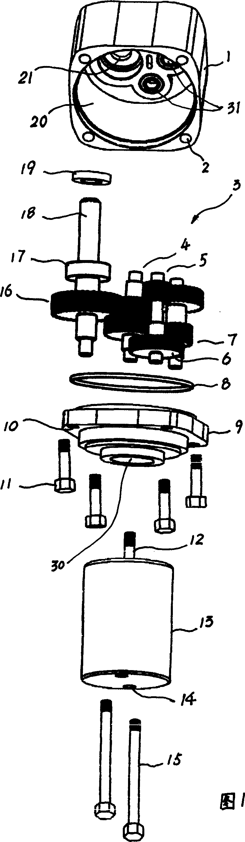
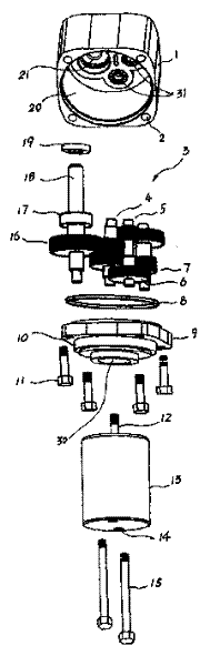
[0010] As shown in the figure, 1_reduction box, 2_threaded hole, 3_reduction mechanism, 4_the third transmission part of the deceleration mechanism, 5_the first transmission part of the deceleration mechanism, 6_the first transmission part gear of the deceleration mechanism, 7_the gear of the deceleration mechanism The second transmission part, 8_sealing ring, 9_end cover, 10_through hole, 11_screw, 12_motor drive shaft, 13_motor, 14_through hole, 15_screw, 16_fourth transmission part of the reduction mechanism, 17_bearing, 18_reduction mechanism output shaft, 19_ oil seal, 20_ airtight chamber, 21_ shaft seam, 30_ through hole, 31_ accommodating hole.

[0011] Referring to FIG. 1 , a motor reduction gearbox includes a motor 13 , a reduction box body 1 , an end cover 9 and a gear reduction mechanism 3 . The gear reduction mechanism 3 is a four-stage gear reduction mechanism, which is arranged in a closed chamber between the reduction box body 1 and the end cover 9 . The four-...


PUM


Abstract

The invention relates to a reduction gear box in electric machine, including electric machine, reduction box and reduction gear; the reduction gear is set in the reduction box and the first driving component of the reduction gear is connected to the driving shaft of the electric machine, and the electric machine is directly connected to the reduction box by an end cover. Thus, the reduction box and the electric machine share the same end cover, largely simplifying the whole structure to make it simpler and more convenient to manufacture and assemble; synchronously, beneficial to control the sealing and working properties of the whole machine. It sets seal washer between the reduction box and the end cover and sets oil seal at the shaft-outlet stop mouth of the reduction box, reducing the leakage of gear lubricant in the reduction box as far as possible and enhancing the sealing property. The reduction and the end cover are made by precision manufacturing device, ensuring the precise installation driving shafts at all levels of the reduction gear.

Description

technical field [0001] The invention relates to a motor reduction gearbox. Background technique [0002] In the known technology, such as the 70JB type motor reduction gear box produced by our company, it includes a motor, a reduction box body and a gear reduction mechanism; the gear reduction mechanism adopts four-stage reduction, and is arranged in the reduction box body. A transmission part is connected to the drive shaft of the motor, and the output shaft is pivotally connected to the box body through bearings; one end of the motor is provided with an end cover, which is connected to the end of the reduction box body after being positioned by a pressure plate cover. The motor gearbox with this structure has many parts and a relatively complicated structure, which not only has high manufacturing cost, complicated manufacturing process and high manufacturing difficulty, but also is not conducive to controlling the sealing of the motor. [0003...

Claims


Application Information

Patent Timeline
Patent Type & Authority Applications(China)
IPC IPC(8): F16H1/20H02K7/116
Inventor 季福生黄海燕朱智平
Owner ZHEJIANG LINIX MOTOR
Why Eureka
Try Eureka