Control devices for internal combustion engines
A technology for control devices and internal combustion engines, applied to control devices for cooling devices, engine control, fuel injection control, etc., can solve problems that cannot be effectively eliminated, and achieve suppression of pre-ignition, omission of detection mechanisms, and simplification of control systems and sensor systems Effect
- Summary
- Abstract
- Description
- Claims
- Application Information
AI Technical Summary
Problems solved by technology
Method used
Image
Examples
Embodiment approach 1
[0057] [Structure of Embodiment 1]
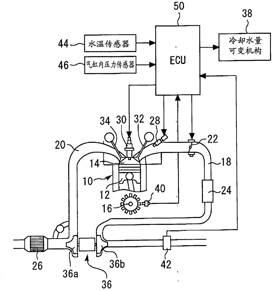
[0058] Below, refer to figure 1 and Figure 8 Embodiment 1 of the present invention will be described. figure 1 It is an overall configuration diagram for explaining the system configuration of Embodiment 1 of the present invention. The system of the present embodiment is equipped with an engine that is a multi-cylinder internal combustion engine. In addition, in figure 1 In , only one cylinder of the engine 10 is shown. In addition, the present invention is applicable to an engine having any number of cylinders including a single cylinder. In each cylinder of the engine 10, a combustion chamber 14 is demarcated by a piston 12, which is connected to a crankshaft 16 of the engine. Also, the engine 10 is equipped with an intake passage 18 for taking intake air into the combustion chamber 14 (inside the cylinder) of each cylinder, and an exhaust passage 20 for discharging exhaust gas from each cylinder.
[0059] Intake passage 18 is pro...
Embodiment approach 2
[0091] Second, refer to Figures 9 to 11 , Embodiment 2 of the present invention will be described. The present embodiment is characterized in that, in addition to the same configuration and control as in the above-mentioned embodiment, control corresponding to a change in fuel properties is also performed. In addition, in this embodiment, the same code|symbol is attached|subjected to the same component as Embodiment 1, and the description is abbreviate|omitted.
[0092] [Features of Embodiment 2]
[0093] As described above, in particular, the relationship between the cylinder wall temperature at low temperature and the frequency of occurrence of pre-ignition is greatly influenced by the occurrence of fuel dilution (volatility of fuel). That is, the Figure 4 The shown characteristic line (temperature lower limit value t1 and temperature upper limit value t2) is obtained based on a certain reference state such as the case of gasoline (the alcohol concentration in the fuel ...
Embodiment approach 3
[0106] Second, refer to Figure 12 , Embodiment 3 of the present invention will be described. The present embodiment is characterized in that only the lower limit value of the temperature in the pre-ignition suppression temperature region is made variable in the same structure and control as in the first embodiment described above. In addition, in this embodiment, the same code|symbol is attached|subjected to the same component as Embodiment 1, and the description is abbreviate|omitted.
[0107] [Feature of Embodiment 3]
[0108] Originally, it is preferable that the temperature upper limit t2 of the pre-ignition suppression temperature region be set based on the occurrence frequency of pre-ignition. However, due to, for example, the structural characteristics of the engine or the surrounding temperature environment (heat resistance, etc.), it may be difficult to shift the cylinder wall temperature t to a high temperature side higher than the temperature upper limit value t2...
PUM
 Abstract
Description
Claims
Application Information
 - R&D
- Intellectual Property
- Life Sciences
- Materials
- Tech Scout
- Unparalleled Data Quality
- Higher Quality Content
- 60% Fewer Hallucinations
Browse by: Latest US Patents, China's latest patents, Technical Efficacy Thesaurus, Application Domain, Technology Topic, Popular Technical Reports.
© 2025 PatSnap. All rights reserved.Legal|Privacy policy|Modern Slavery Act Transparency Statement|Sitemap|About US| Contact US: help@patsnap.com


