
commutator manufacturing method

A manufacturing method and commutator technology, which is applied in commutator manufacturing and other directions, can solve the problems of excessive wear of carbon brushes, deformation of the plastic substrate of the commutator, and high noise, so as to prolong service life, ensure performance, and improve The effect of service life

Inactive Publication Date: 2016-06-22
重庆松普电器有限公司
View PDF5 Cites 0 Cited by
  • Summary
  • Abstract
  • Description
  • Claims
  • Application Information

AI Technical Summary

Problems solved by technology

[0003] The commutator produced by the above process has the following defects: 1) After long-term use, the plastic matrix of the commutator will be deformed and cracked, resulting in jumping pieces and flying pieces; 2) The insulating groove is processed by milling cutters , there will inevitably be burrs in the insulation groove, which will cause large noise, excessive wear of carbon brushes, etc., and affect the operation performance of the motor

Method used


Image

  • commutator manufacturing method

Examples


Embodiment Construction

[0024] The commutator of this embodiment is realized through the following process steps:

[0025] (1) Copper is used as raw material, and the material is cut and drawn into copper bars;

[0026] (2) Punch commutator segments on the copper bars;

[0027] (3) Cleaning the punched commutator segments;

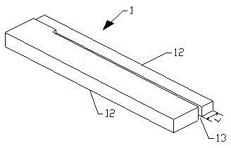
[0028] (4) The mica sheet 1 is cut into strips and punched into shape. The width of the inner side 11 of the mica sheet is the same as the width of the insulating groove, and the width of the outer side 12 is slightly narrower than the width of the insulating groove. Moreover, the connection between the inner side and the outer side of the mica sheet stamping a breakable notch 13;

[0029] (5) Arranging the commutator slices and mica slices 1;

[0030] (6) Put the component circle formed by the arrangement of the commutator piece and the mica piece 1 into the injection mold, and injection mold it into a commutator;

[0031] (7) Curing;

[0032] (8) boring;

[0033] (9) Turn...


PUM


Abstract

The invention relates to a method for manufacturing a commutator. The geometric shape and size of the insulating groove of the commutator are guaranteed by mica sheets, and a notch is punched out during the mica sheet punching process, and then centrifugal force is used in the secondary molding process of rotary heating Separating the outside and inside of the mica sheet from the notch, without milling or manually breaking off the outside of the mica sheet, the insulation groove can be formed naturally without burrs in the groove, which prolongs the life of the commutator The service life of the motor ensures the performance of the motor; after secondary molding by rotary heating, the internal stress of the plastic matrix of the commutator can be kept in balance, preventing the plastic matrix from being torn and deformed during the use of the commutator, which can greatly improve the commutation performance. life of the guide.

Description

technical field [0001] The invention relates to a commutator manufacturing method. Background technique [0002] The molding process of the plastic matrix commutator in the prior art is generally as follows: 1. The blanking and pulling of the commutator segment; 2. Punching the commutator segment and cutting the mica sheet into strips; Carry out mica slice punching; 4. Arrange the commutator slices, and use mica slices for interval insulation between the commutator slices; 5. Put the arranged commutator slice rings into the injection mold for injection molding; 6. Curing; 7. Boring; 8. Turning; 9. Milling wiring slots, milling insulation slots; 10. Passing the inspection. [0003] The commutator produced by the above process has the following defects: 1) After long-term use, the plastic matrix of the commutator will be deformed and cracked, resulting in jumping pieces and flying pieces; 2) The insulating groove is processed by milling cutters , There will inevitably be bur...

Claims


Application Information

Patent Timeline
Patent Type & Authority Patents(China)
IPC IPC(8): H01R43/06
Inventor 郑胜利
Owner 重庆松普电器有限公司
Learn More