
Perforating apparatus and method for slab workpiece

A technology for plate-shaped workpieces and hole positions, which is applied to feeding devices, boring/drilling, automatic control devices, etc., can solve the problems of hindering the installation and removal of the fixture plate 14, and the time-consuming and laborious replacement of the fixture plate 114. It is easy and The effect of quick job changes

Inactive Publication Date: 2004-09-08
SEIKO PRECISION CO LTD
View PDF1 Cites 14 Cited by
  • Summary
  • Abstract
  • Description
  • Claims
  • Application Information

AI Technical Summary

Problems solved by technology

[0006] However, in the above-mentioned conventional drilling device, since the jig plate 114 is mounted on the workbench 111 on the main body side, when the jig plate 114 is replaced according to the type of the printed circuit board P, etc., it is used for detection and recognition. Peripheral equipment such as a marked camera or a punch for drilling holes in the printed circuit board P will hinder the attachment and detachment of the jig plate 14, and there is a problem that the replacement of the jig plate 114 is time-consuming and laborious.

Method used


Image

  • Perforating apparatus and method for slab workpiece
  • Perforating apparatus and method for slab workpiece
  • Perforating apparatus and method for slab workpiece

Examples


Embodiment Construction

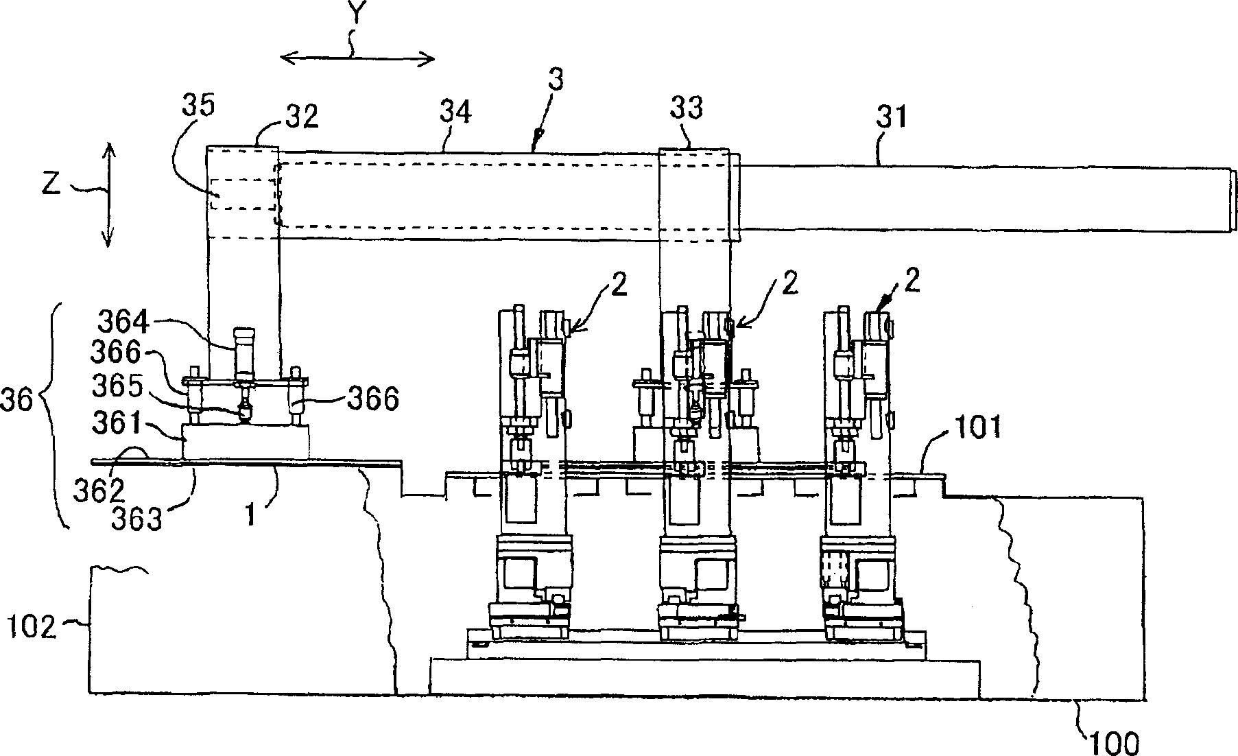
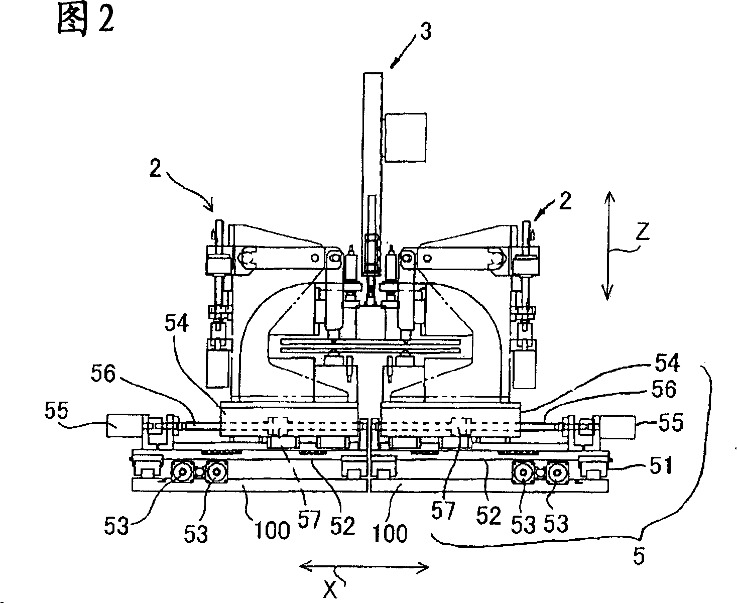
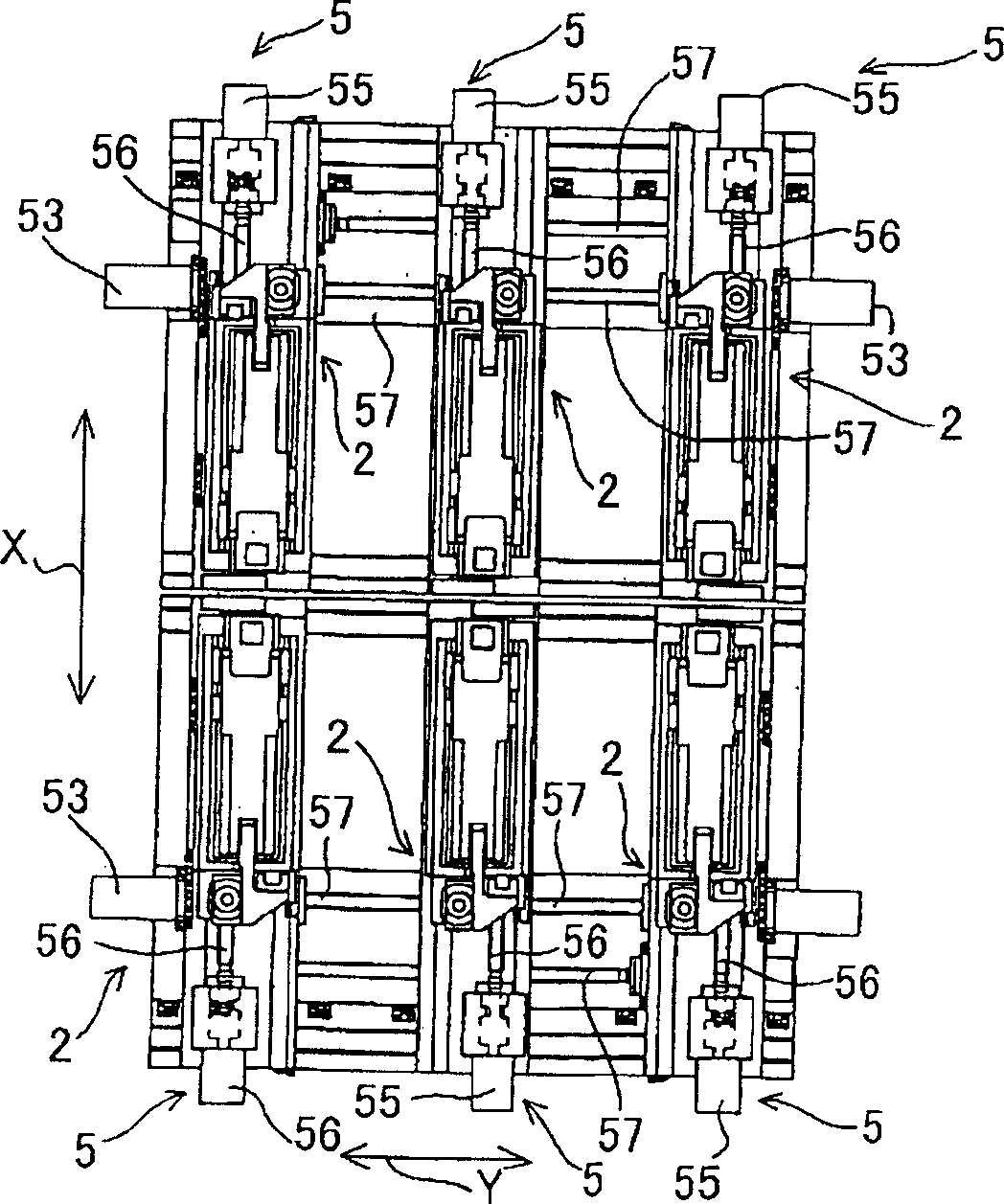
[0027] Below, refer to Figure 1 to Figure 11 , and the structure of the drilling device for a plate-shaped workpiece to which the present invention is applied will be described. First, a general description of the overall structure is given. In this hole-drilling device, there are 6 hole-drilling mechanisms 2 for punching holes in the plate-shaped workpiece 1, and the input mechanism 3 that holds the plate-shaped workpiece and transports the plate-shaped workpiece to the hole-opening mechanism is respectively connected with the plate-shaped workpiece. The hole opening mechanisms are provided as an integral camera mechanism 4 and a moving mechanism 5 capable of moving each hole opening mechanism independently of each other. Also, the hole opening device has processing such as Figure 10 The image processing mechanism 6 of the imaging result of the imaging mechanism 4 shown, the computing mechanism 7 that calculates the processing result of the image processing mechanism, and...


PUM


Abstract

The fixture plate 362 provided with a plurality of reference holes 362f is detachably provided on a chuck 36 transferring the plate-like work 1 to a boring part while sucking and retaining it. The chuck 36 for adsorbing and retaining the plate-like work 1 also has a function of the fixture plate 362. Therefore, it is not required that the fixture plate 362 is separately manufactured and installed and outstanding cost reduction is realized. The exchange work of the fixture plate can be extremely easily and quickly carried out by detachably providing the fixture plate 362 on the chuck.

Description

technical field [0001] The invention relates to a hole-drilling device and a hole-drilling method for a plate-shaped workpiece, in particular to a hole-drilling device and a hole-drilling method for a printed circuit board. Background technique [0002] In electronic devices and the like, multilayer printed wiring boards in which a plurality of substrates on which circuit patterns are formed are laminated and fixed are widely used. However, when the positions of the circuit patterns are shifted from each other when the substrates are laminated, the predetermined functions and performances of the printed wiring board cannot be fully exhibited. To this end, at least two guide holes should be provided at the specified positions of each substrate, and the guide shaft of the jig should be inserted into the guide holes to realize the positioning of each substrate. Since the mutual positional accuracy when laminating the substrates is determined based on the positional accuracy of...

Claims


Application Information

Patent Timeline
IPC IPC(8): B23Q15/00B23B39/06B23B41/00B23Q17/24B26F1/04G05B19/19H05K3/00
CPCB26D5/00B26D7/00B26D7/01B26F1/04B26F1/14
Inventor 东海林健
Owner SEIKO PRECISION CO LTD
Learn More