Method for detecting fault of steel-ball surface

A detection method and a technology of steel balls, which are applied in the direction of optical testing of flaws/defects, measuring devices, and material analysis through optical means, and can solve problems such as misjudgment detection efficiency and missed detection

Inactive Publication Date: 2004-09-15
李季秀
View PDF0 Cites 51 Cited by
  • Summary
  • Abstract
  • Description
  • Claims
  • Application Information

AI Technical Summary

Problems solved by technology

[0003] The purpose of the present invention is to provide a detection method for steel ball surface defects with accurate detection and high efficiency in order to solve the problems of missed detection, misjudgment and low detection efficiency in the existing steel ball surface defect detection method

Method used


Image

  • Method for detecting fault of steel-ball surface
  • Method for detecting fault of steel-ball surface
  • Method for detecting fault of steel-ball surface

Examples


Embodiment Construction

[0015] Method of the present invention comprises the following steps:

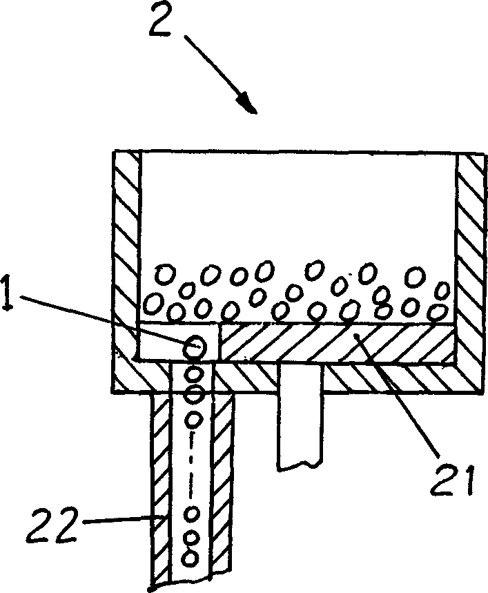
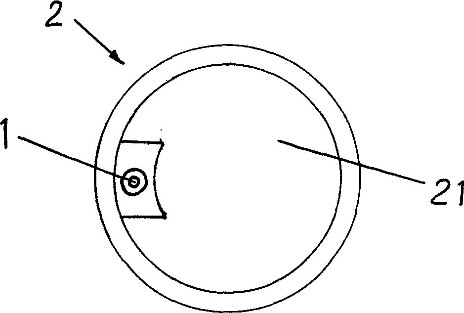
[0016] 1. See figure 1 As shown, put the steel ball 1 to be tested into the feeding mechanism 2;

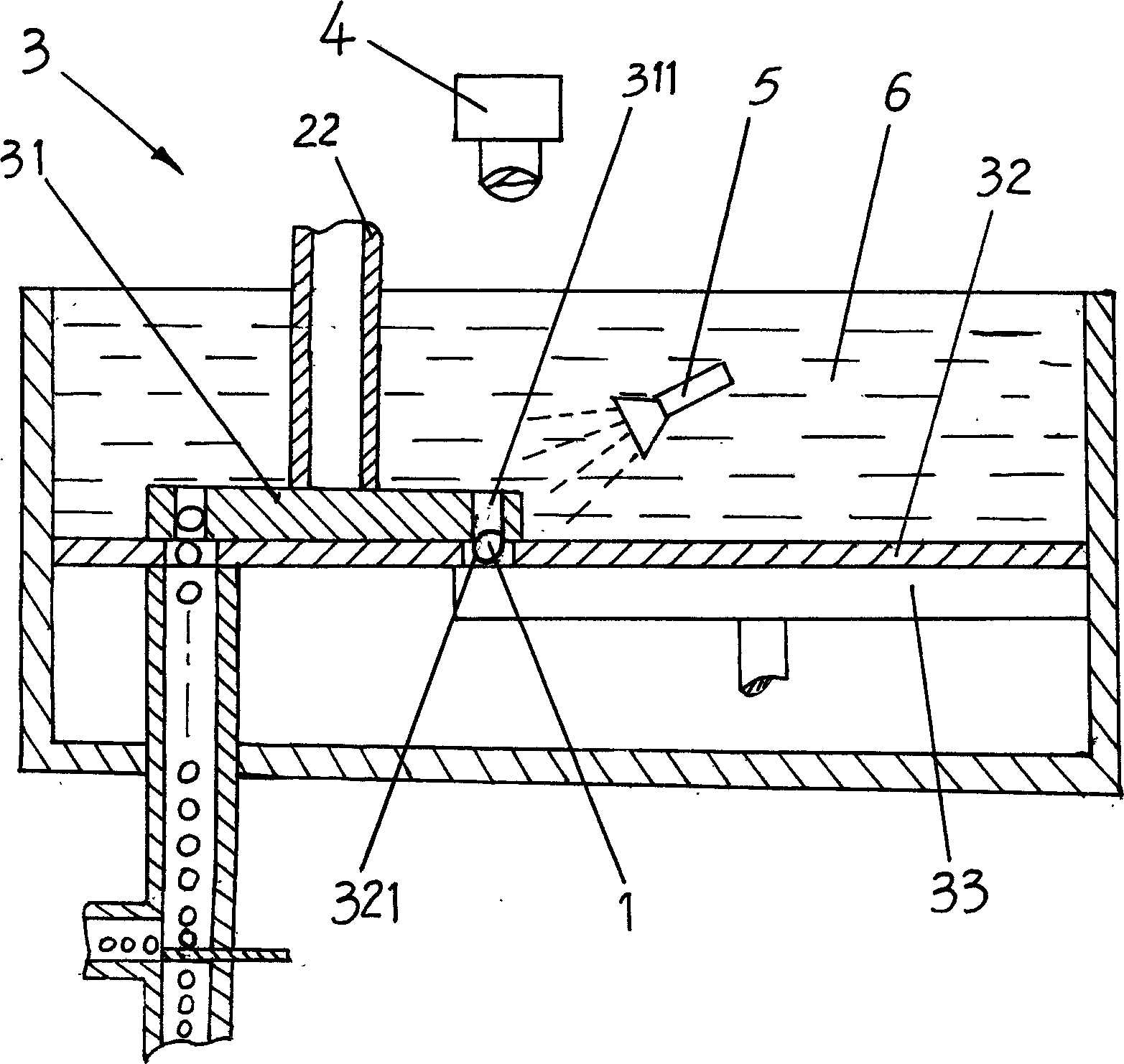
[0017] 2. By the reciprocating rotation of the ball dial 21 in the feeding mechanism 2, the steel balls are smoothly sent from the material guide tube 22 into the hole-shaped detection chamber 311 on the periphery of the feeding turntable 31 in the detection mechanism 3, as image 3 As shown, the feed turntable is made of white light-transmitting material, and a partition 32 is provided under the feed turntable 31 to provide a supporting surface. 321 corresponds to the hole-shaped detection chamber 311 on the feed turntable 31, the feed turntable 31 rotates step by step, and the steel balls 1 are pushed into the holes 321 of the partition 32 in sequence, and the unfolding turntable 33 arranged under the partition 32 acts as The swinging and rotating movement drives the steel ball 1 in the hole 321 of the pa...


PUM


Abstract

Feed mechanism feeds balls to be tested to poroid detection cavity positioned on circumference of feeding rotary table and holes corresponding to clapboard positioned under feeding rotary table in detection mechanism. Balls to be tested on feeding rotary table and its holes are immersed in kerosene. The deploying rotary table under the clapboard supports balls to be tested to rotate in order to expanse entire spherical surface. CCD camera above the balls collects information of extended surface of balls to be tested. The said collected information is input into and processed by computer. Display in terminal displays magnified image of extended surface of rolled ball. Computer recognition system through magnified image on the display determines surface quality of the ball. Thus, qualified balls are sent to finished product bin, and unqualified balls are sent to reject bin in automatic or manual control. The method is in high accuracy and high efficiency.

Description

technical field [0001] The invention relates to a detection method for surface defects, in particular to a detection method for steel ball surface defects. Background technique [0002] The existence of surface defects of bearing steel balls affects the accuracy and service life of bearings. At present, domestic bearing manufacturers generally observe and detect with human eyes. The detection efficiency is low and the quality is difficult to guarantee. Moreover, the workers who operate are generally young people. However, after the inspectors used their eyes for about three years, the damage to the eyes was particularly large, which caused great harm to people's health. Some foreign countries use testing equipment to detect, such as the "Bearing Steel Ball Photoelectric Appearance Detector" produced in Japan, and the "Bearing Steel Ball Eddy Current Flaw Detector" produced in the United States. Using the above equipment to detect steel balls, one instrument can only detect a...

Claims


Application Information

Patent Timeline
Patent Type & Authority Applications(China)
IPC IPC(8): G01N21/88G01N21/952
Inventor 李季秀
Owner 李季秀
Why Eureka
Try Eureka