
Generator

A technology for power generation devices and generators, applied in circuit devices, signal devices, control generators, etc., can solve problems such as insufficient power, and achieve the effects of prolonging life, simplifying structure, and improving reliability.

Inactive Publication Date: 2004-09-22
HONDA MOTOR CO LTD
View PDF1 Cites 21 Cited by
  • Summary
  • Abstract
  • Description
  • Claims
  • Application Information

AI Technical Summary

Problems solved by technology

However, since this will temporarily limit the output as a result, power shortage will temporarily occur from the load side, which is not desirable for the load

Method used


Image

  • Generator
  • Generator

Examples


Embodiment Construction

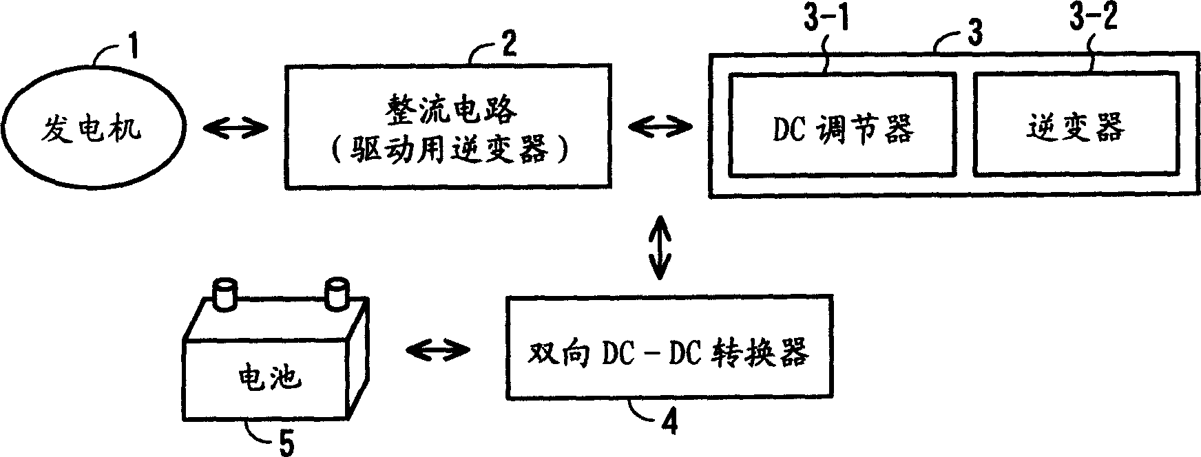
[0018] Hereinafter, the present invention will be described in detail with reference to the drawings. figure 1 is a block diagram showing the concept of the power generating device according to the present invention. In this figure, the generator 1 is constituted by, for example, a three-phase multi-pole magnet generator. In the following embodiments, the generator 1 will be described assuming that the generator 1 is an engine-driven generator connected to and driven by the engine, and a motor-generator that can also operate as an engine starting motor.

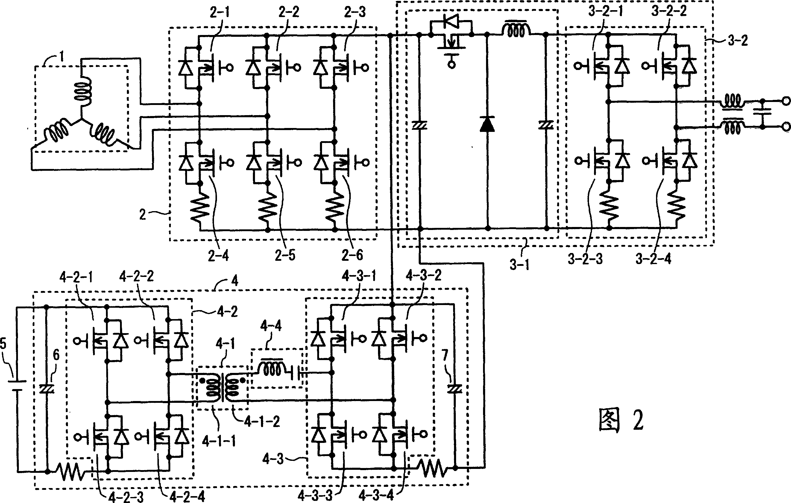
[0019] The rectification circuit 2 has a bridge-connected rectification element, and rectifies the output of the generator 1 . In addition, each rectifying element of the rectifying circuit 2 is connected in parallel to switching elements such as FETs, and these switching elements constitute an inverter for driving that converts the DC voltage into a three-phase AC voltage and applies it to the generator 1 by turning on and ...


PUM


Abstract

The output of a generator (1) is rectified in a rectifier circuit (a drive inverter) (2). The output of the rectifier circuit (2) is converted into AC power of a predetermined frequency in an electronic power inverter section (3). A two-way DC-DC converter (4) is connected between the output side of the rectifier circuit (2) and the output terminal of the battery (5). The battery (5) is charged by the output of the rectifier circuit (2). Electric power is also supplied from the battery (5) to the load through the two-way DC-DC converter (4) when an overloaded state is caused and the output of the generator (1) cannot meet the demand for the load in the state.

Description

technical field [0001] The present invention relates to a power generating device, and more particularly to a power generating device capable of supplementing the insufficient output from a battery when the output of a power generating device such as an engine-driven generator is temporarily insufficient. Background technique [0002] Power generating devices such as engine generators are widely used as power supply devices for various purposes ranging from portable use to emergency use. When a load, such as a mercury lamp load or a motor load, to which a large current flows temporarily at startup is connected to a small-scale power generation device such as an engine-driven generator, an overload state may temporarily occur and the rotation speed of the engine and generator may drop. , causing a stall (shutdown). That is, if a temporary overload state occurs, the rotation speed of the engine decreases, and with this decrease, the output of the power generation device decre...

Claims


Application Information

Patent Timeline
IPC IPC(8): H02P9/10H02J9/06H02M3/335H02P9/04
CPCH02J9/061H02J9/062H02M3/33584Y02B70/1441Y02B70/1491H02M2001/0058Y02B70/10H02M1/0009H02M1/0058E06B7/36G08B5/38G08B6/00G08B3/1033E05Y2800/41
Inventor 江口博之清水元寿
Owner HONDA MOTOR CO LTD
Learn More