Switch

A switch and operating handle technology, applied in the field of switches, can solve the problems of not easy to visually see the operating position of fingers, difficult to distinguish the operating position, etc., and achieve the effect of beautifying the appearance

Inactive Publication Date: 2004-09-29
MATSUSHITA ELECTRIC WORKS LTD
View PDF1 Cites 7 Cited by
  • Summary
  • Abstract
  • Description
  • Claims
  • Application Information

AI Technical Summary

Problems solved by technology

[0005] However, in such Figure 33 and Figure 34 In the switch shown, since the color of the front of the operating handle 60' is the same as the color of the front of the decorative plate installed in front of the installation frame, it is not easy to visually see the operating position of the finger, and it is difficult to distinguish the operating position.

Method used


Image

  • Switch
  • Switch
  • Switch

Examples


Embodiment 1

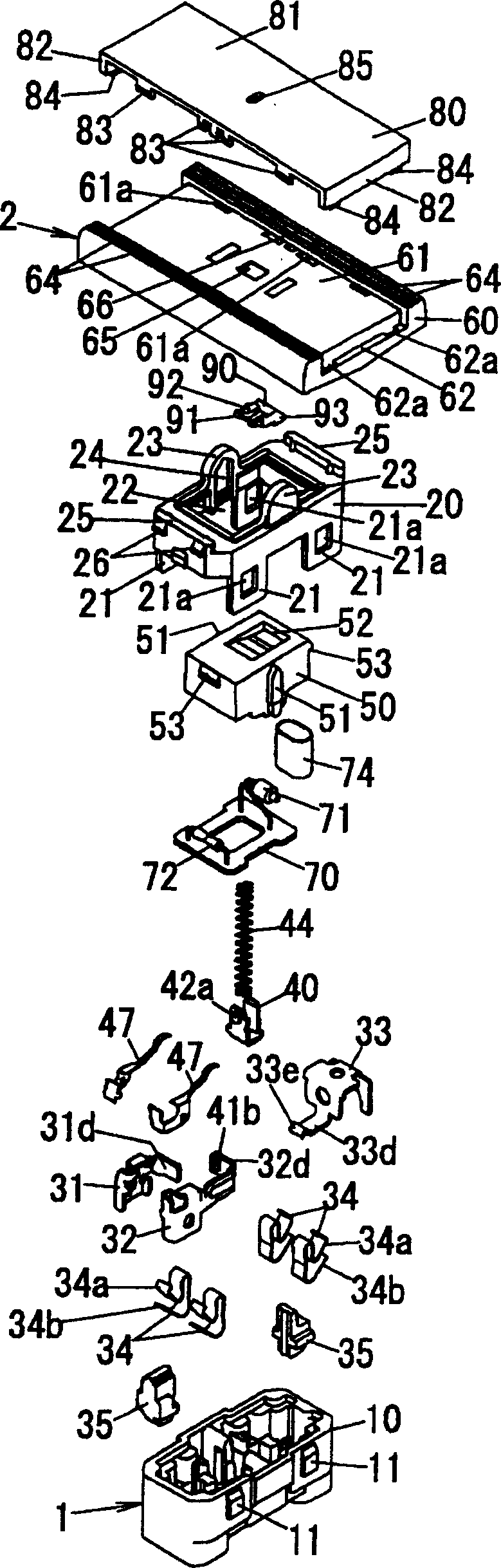
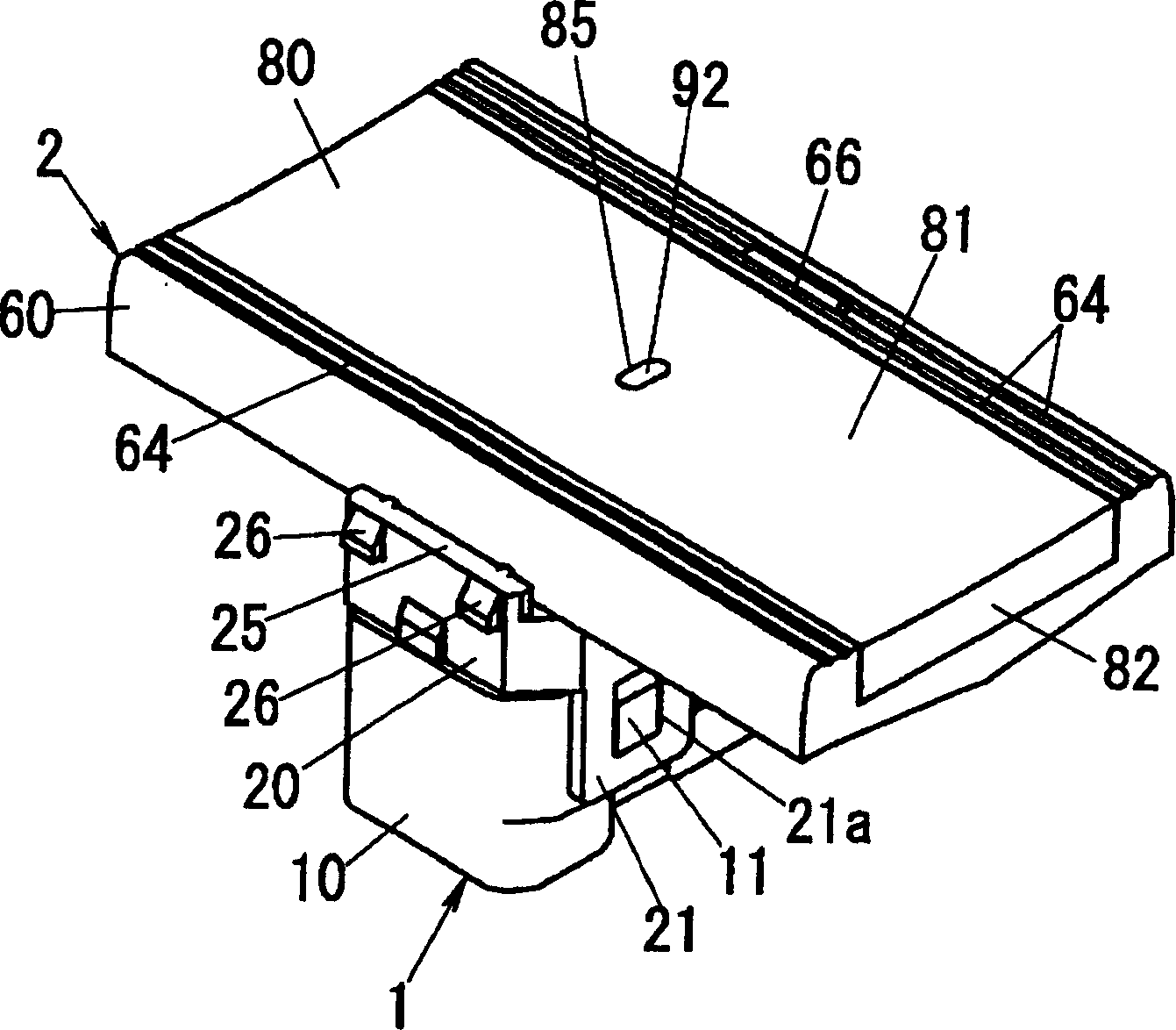
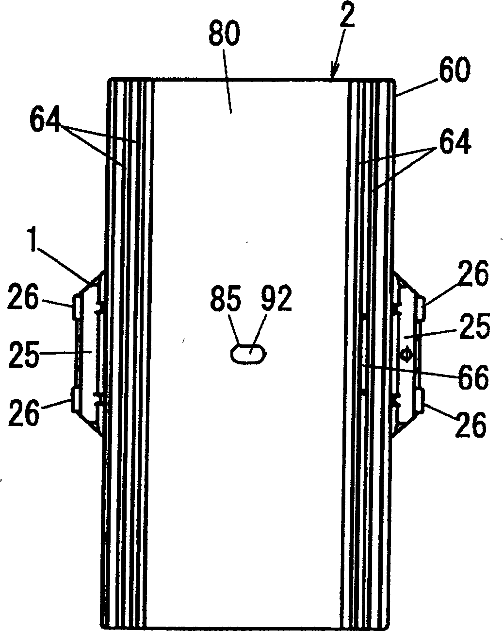
[0050] The switches of this embodiment, such as Figure 1 ~ Figure 4 As shown, there is a body 1 composed of a rectangular parallelepiped synthetic resin molded case 10 with an open front and a synthetic resin molded cover 20 formed in a rectangular frame shape and joined to the front side of the case 10 . On the two outer sides in the width direction (transverse direction) of the housing 10, a pair of mounting protrusions 11 are projected at intervals in the longitudinal direction of the housing 10, and a mounting tongue 21 is extended backward from the rear end edge of the cover 20. , engage the fitting protrusion 11 in the fitting hole 21 a provided on the fitting tongue 21 , and thus combine the case 10 and the cover 20 .

[0051] Regarding the housing 10, at one end in the longitudinal direction ( Figure 4 The left end of the center) accommodates two terminal boards 31, 32, and the other end ( Figure 4 A terminal board 33 is accommodated in the right end portion of th...

Embodiment 2

[0079] The basic structure of the switch of this embodiment is roughly the same as that of Embodiment 1, as Figure 12 As shown, the dimensions of the operating handle body 60 and the handle cover 80 are different from those of the first embodiment. That is, in this embodiment, the size of the operating handle 2 is different from that of the operating handle 2 for one described in the first embodiment. In addition, the same code|symbol is attached|subjected to the same component as Example 1, and description is abbreviate|omitted.

[0080]The operating handle 2 of this embodiment is called the operating handle 2 for two because the operating handle main body 60 is formed to cover the size of the two window holes 120a of the mounting frame or the plate frame 120 . That is, the size of the operating handle 2 for two is the same as that of the operating handle 2 for one in the direction along the widthwise direction of the window hole 120a of the plate frame 120, and the dimensi...

Embodiment 3

[0082] The basic structure of the switch of this embodiment is roughly the same as that of Embodiment 1, as Figure 22 and 23 As shown in (a), the dimensions of the operating handle main body 60 and the handle cover 80 are different from those of the first embodiment. That is, in this embodiment, the size of the operating handle 2 is different from that of the operating handle 2 for one described in the first embodiment. In addition, the same code|symbol is attached|subjected to the same component as Example 1, and description is abbreviate|omitted.

[0083] The operating handle 2 of this embodiment is called a three-purpose operating handle 2 because the operating handle main body 60 is formed with the size of the three window holes 120a covering the installation frame or the plate frame 120 . That is, the size of the operating handle 2 for three is the same as that of the operating handle 2 for one in the direction along the widthwise direction of the window hole 120a of t...


PUM


Abstract

Provided is a switch capable of easily, visually identifying the operation position of an operation handle. The switch is provided with a reverse handle 50 that is retained on the front side of an equipment body 1 so that the reverse handle can be rocked with respect to the equipment body 1 and changes a contact in the equipment body 1; and an operation handle 2 that is arranged in the opening window of a decorating plate that is connected to the front side of the reverse handle 50 and is attached to the front of a plate frame and has both ends that alternately perform the raising and falling operation by alternately pushing down both the ends. The operation handle 2 comprises an operation handle body 60 connected to the reverse handle 50, and a handle cover 80 that is deposited to the front side of the operation handle body 60 while the front of both the ends of the operation handle body 60 is exposed. The color of the operation handle body 60 is made different from those of the handle cover 80 and decoration plate.

Description

technical field [0001] The present invention relates to a switch. Background technique [0002] In the past, the switches provided include: wave switch, an operating handle is installed on the front side of the body that can be installed on the mounting frame for embedded wiring appliances, and the contacts are switched by alternately pressing the two ends of the operating handle; A switch (for example, refer to Patent Document 1) includes a switch main body for switching contacts in the body by pressing a button handle provided on the front side of the body, and in a form facing the front of the switch body, the A key handle that is rotatably mounted on the switch body at one end and can be pressed into the button handle. Furthermore, in the key lever switch, the key lever constitutes an operating handle. [0003] However, as the operating handle of the above-mentioned rocker switch, the following configuration has been proposed, for example, as Figure 33 As shown, in th...

Claims


Application Information

Patent Timeline
Patent Type & Authority Applications(China)
IPC IPC(8): H01H23/14H01H9/18H01H21/02H01H21/22H01H23/24
Inventor 氏原秀哲矢野学
Owner MATSUSHITA ELECTRIC WORKS LTD
Why Eureka
Try Eureka