Cut-off filtering composite valve

A combined valve and filter cavity technology, which is applied in the direction of filtration separation, valve lift, valve device, etc., can solve the problems of short service life of valves, blockage of pipeline valves, and single function, so as to prolong service life, reduce manufacturing costs, and improve The effect of overhaul efficiency

Inactive Publication Date: 2004-10-06
方吉全
View PDF0 Cites 7 Cited by
  • Summary
  • Abstract
  • Description
  • Claims
  • Application Information

AI Technical Summary

Problems solved by technology

[0002] The plunger valve in the known technology, the shut-off valve and the filter have different structures and functions and are also used in different occasions. They have a single function and are used alone.
Especially for plunger valves and globe valves used in pipelines with impurities in liquid (gas), the pipelines and valves are often blocked due to impurities in the fluid, resulting in short service life of the valves and frequent maintenance of pipelines or replacement of valves.

Method used


Image

  • Cut-off filtering composite valve
  • Cut-off filtering composite valve
  • Cut-off filtering composite valve

Examples


Embodiment 1

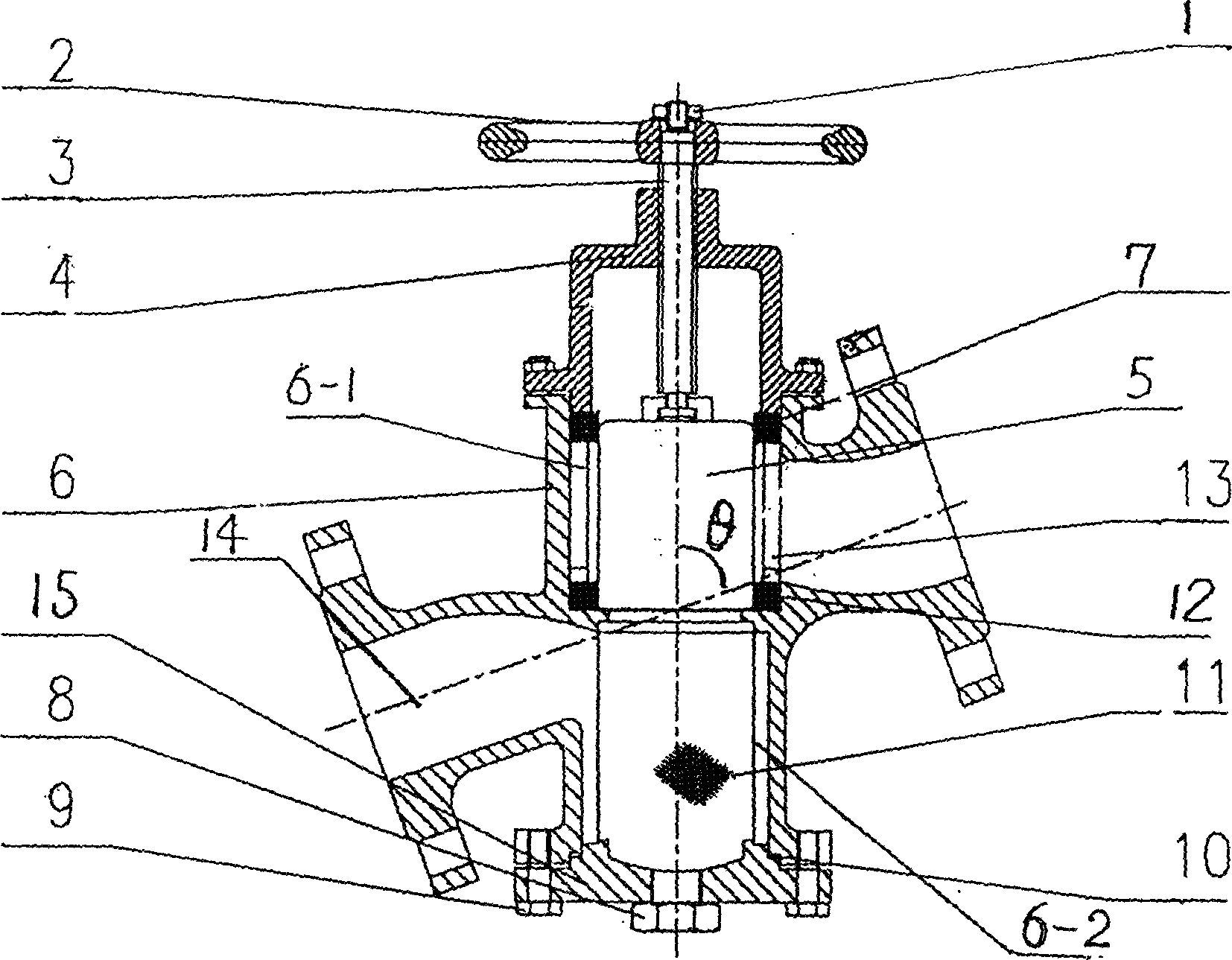
[0012] Such as figure 1 The plunger-type cut-off filter combination valve shown has a plunger valve part composed of a valve body 6, a valve cover 4, a valve stem 3 and a plunger 5 with the same structure as the known technology, and is characterized in that it will The valve body is set in two parts, the upper cut-off cavity 6-1 and the lower filter cavity 6-2, the hand wheel 2 is fastened to the upper end of the valve stem 3 through the valve stem nut 1, and the valve cover 4 is sealed on the upper port of the valve body 6, and its The valve stem 3 passes through the valve cover 4 and its lower end is connected with the cylindrical plunger 5 in the valve body. The upper sealing ring 7 and the lower sealing ring 12 in the cut-off cavity are respectively placed at the upper and lower ports of the valve body inlet, and the valve body inlet 13 It communicates with the cut-off cavity, and the outlet 14 of the valve body communicates with the lower filter cavity of the valve body ...

Embodiment 2

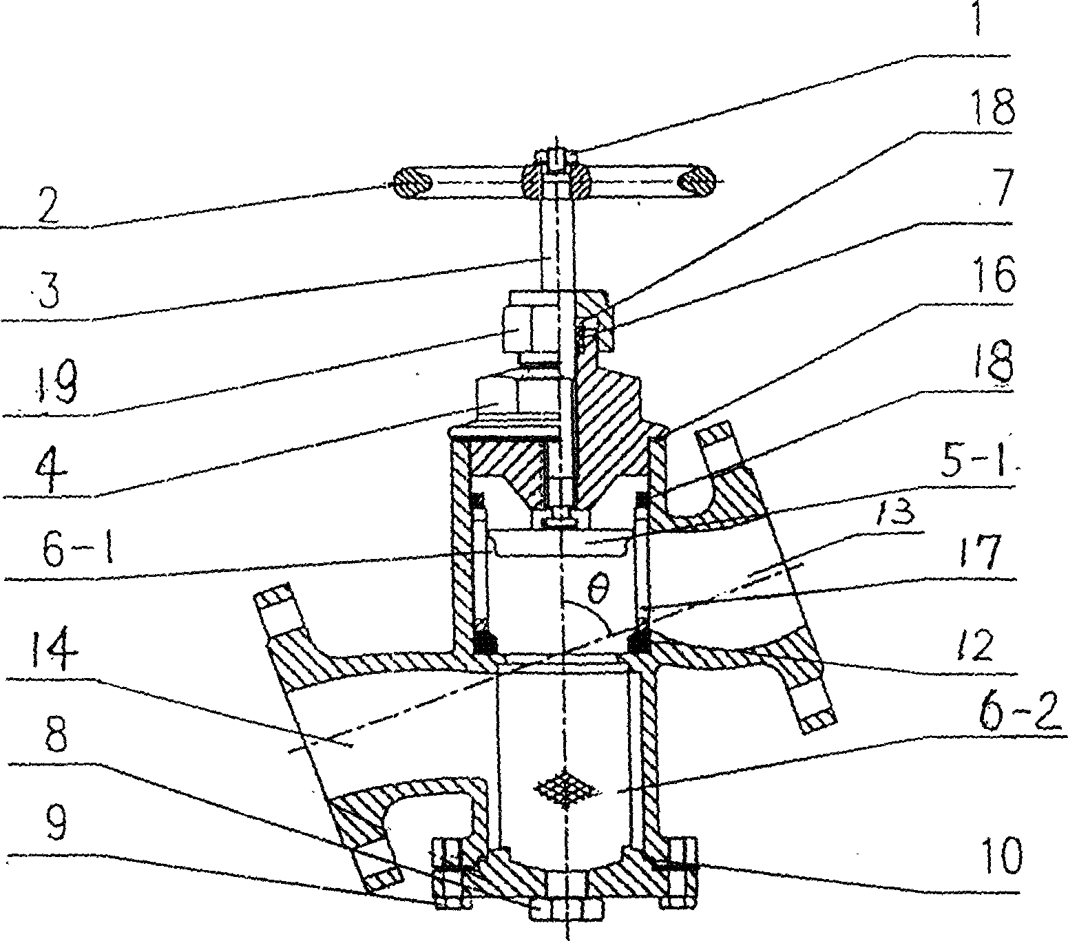
[0014] Such as figure 2 Another novel plunger-type cut-off filter combination valve shown is an improvement on the basis of known plunger-type cut-off valves. It sets the valve body of the plunger valve into two parts, the upper cut-off chamber 6-1 and the lower filter chamber 6-2, the inlet 13 of the valve body communicates with the cut-off chamber, and the outlet 14 of the valve body is connected with the cylindrical filter. According to the structure of the valve body and the best flow direction of the connecting pipeline, the axes of the cut-off cavity and filter cavity of the valve body and the connecting axis of the inlet and outlet pipelines of the valve body form a positive angle of θ<90° . The difference from the plunger valve in Embodiment 1 is that the plunger 5-1 used in the cut-off chamber 6-1 vertically connected to the filter chamber 6-2 and the lower sealing elastic ring 12 installed on the sealing platform of the valve body have at least two The composite s...

Embodiment 3

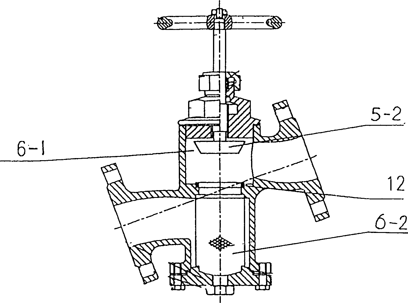
[0016] Such as image 3 What is shown is a disc-type cut-off filter combined valve. On the basis of the improved parts of Embodiments 1 and 2, the different parts of the plunger valve are the ones used in the plunger chamber 6-1 vertically connected to the filter chamber 6-2. The cut-off disc plunger 5-2 and the cut-off gasket 12 are standard structures of known technologies. The inlet and outlet of the valve body are connected with the pipeline by flanges.


PUM


Abstract

A combined cutt off-filter valve integrating the plunger valve with filter is composed of valve body, valve cover, valve rod, plunger, and cylindrical net filter installed in the filter cavity of valve body. Its advantages are both cut-off and filter functions, and long service life.

Description

technical field [0001] The invention belongs to the field of valves, in particular to a cut-off filter combination valve in which a plunger (cut-off) valve and a filter are integrated. Background technique [0002] The plunger valve in the known technology, shut-off valve and strainer structure function are different and the occasion of use is also different, and effect is single, and all is used alone. Especially for plunger valves and globe valves used in pipelines with impurities in liquid (gas), the pipelines and valves are often blocked due to impurities in the fluid, resulting in short service life of the valves and frequent maintenance of pipelines or replacement of valves. . Contents of the invention [0003] The technical problem to be solved by the present invention is to overcome the defects of the above-mentioned plunger (stop) valve used in pipelines with impurities in liquid (gas) and provide a cut-off filter combination with one-way cut-off and filter funct...

Claims


Application Information

Patent Timeline
Patent Type & Authority Applications(China)
IPC IPC(8): B01D35/04F16K1/00F16K13/00
Inventor 方吉全
Owner 方吉全
Why Eureka
Try Eureka