Magnetic RAM and its reading-out method

A technology of random access memory and memory unit, which is applied in the direction of static memory, digital memory information, information storage, etc.

Inactive Publication Date: 2004-10-06
KK TOSHIBA
View PDF2 Cites 8 Cited by
  • Summary
  • Abstract
  • Description
  • Claims
  • Application Information

AI Technical Summary

Problems solved by technology

In this way, it is difficult to introduce MRAM into

Method used


Image

  • Magnetic RAM and its reading-out method
  • Magnetic RAM and its reading-out method
  • Magnetic RAM and its reading-out method

Examples


no. 1 example

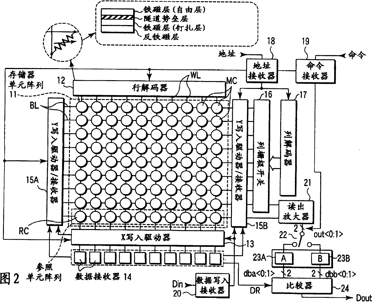
[0038] FIG. 2 shows an MRAM according to a first embodiment of the present invention. In the memory cell array 11, a plurality of memory cells MC having, for example, TMR as a basic element are arranged in a matrix. These memory cells MC are connected to word line WL and bit line BL, respectively. One end of each word line WL is connected to the row decoder 12 , and the other end of each word line WL is connected to the X write driver 13 . The X write driver 13 generates a current magnetic field in the X-axis direction by the current flowing in the word line WL.

[0039] For example, a column closest to the X write driver 13 in the memory cell array 11 is used as a reference cell RC that plays an important role in realizing non-destructive reading. These reference cells RC are connected to dedicated bit lines.

[0040] The same number of reference cell data registers 14 as the number of reference cells RC are arranged in the X write driver 13 . These data registers 14 hold...

no. 2 example

[0073] Fig. 13 shows a block diagram of the MRAM of the second embodiment. In FIG. 13, the same parts as those in FIG. 2 have the same symbols. The second embodiment differs from the first embodiment in the structure of a memory cell array using TMR. That is, in the memory cell array 11 of the first embodiment, the memory cells MC and the reference cells RC are arranged at all intersections of the word lines WL and the bit lines BL, and bit lines dedicated to the reference cells RC are arranged in the memory cell array 11. It is located adjacent to the X write driver 13.

[0074] In contrast, in the second embodiment, as shown in FIG. 13 , memory cells MC and reference cells RC are arranged only in half of the intersections of word lines WL and bit lines BL. Reference cells RCA, RCB are arranged in the row direction, and word lines WL dedicated to reference cells RC are arranged at both ends of memory cell array 11 adjacent to Y write driver / receiver 15A, 15B.

[0075] Memo...


PUM


Abstract

Reference cells are provided in a memory cell array. When the data is read, the data in the reference cells are inverted, thereby preventing the data in the selected cell from changing. This makes it possible to decrease the number of write operations and realize a high-speed read operation and lower power consumption.

Description

[0001] Cross References to Related Applications [0002] This application is based on and claims priority from prior Japanese Patent Application No. 2003-38723 filed on February 17, 2003, the contents of which are incorporated herein by reference in their entirety. technical field [0003] The present invention relates to, for example, a magnetic random access memory (MRAM: Magnetic Random Access Memory), and particularly relates to a method of reading memory information using a reference cell. Background technique [0004] MRAM is a device that stores 1 or 0 data using the magnetoresistance effect, and has been developed as a candidate for conventional memory devices that are non-volatile, highly integrated, highly reliable, low power consumption, and capable of high-speed operation . [0005] As the magnetoresistance effect, two main types are known: GMR (Giant Magneto Resistive) and TMR (Tunneling Magneto Resistive). Among them, GMR uses the effect that the resistance o...

Claims


Application Information

Patent Timeline
IPC IPC(8): G11C11/15
CPCG11C11/15E05B15/0053E05Y2900/516E05Y2900/531
Inventor 土田贤二
Owner KK TOSHIBA
Why Eureka
Try Eureka