Fuel cell and its mfg. method, electronic machine and automobile

一种燃料电池、制造方法的技术,应用在燃料电池、燃料电池的零部件、固体电解质燃料电池等方向,能够解决制造成本增高、使用量增加、工序多等问题,达到低成本、减少使用量的效果

Inactive Publication Date: 2004-10-06
SEIKO EPSON CORP
View PDF2 Cites 2 Cited by
  • Summary
  • Abstract
  • Description
  • Claims
  • Application Information

AI Technical Summary

Problems solved by technology

However, these methods have many steps and are complicated, and it is difficult to uniformly coat the catalyst, and it is difficult to accurately coat a specific amount of catalyst on a specific position, so the characteristics (output density) of the resulting fuel cell may be low or The problem of high production costs due to the increase in the use of expensive catalysts such as platinum

Method used


Image

  • Fuel cell and its mfg. method, electronic machine and automobile
  • Fuel cell and its mfg. method, electronic machine and automobile
  • Fuel cell and its mfg. method, electronic machine and automobile

Examples


Embodiment Construction

[0045] Next, the fuel cell of the present invention, its manufacturing method, electronic equipment, and automobiles will be described in detail.

[0046] 1) Fuel cells

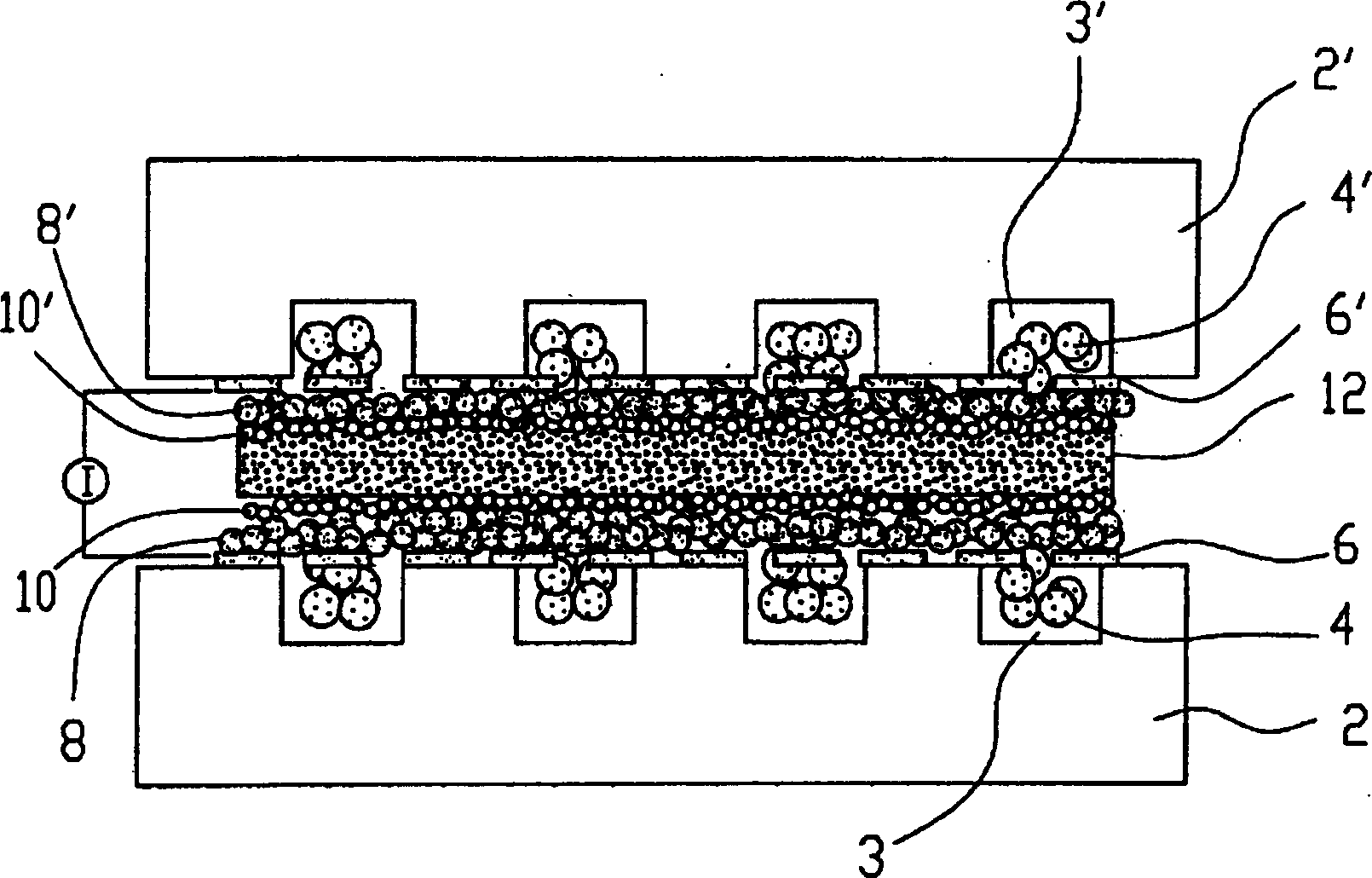
[0047] figure 1 An end view showing the fuel cell of the present invention. figure 1 The fuel cell shown is composed of the following parts starting from the lower side in the figure, that is, a first substrate 2, a first gas flow channel 3 formed on the second substrate 2, and a first gas flow channel housed in the first gas flow channel. 3, the first support member 4, the first collector layer 6 formed on the first substrate 2 and the first support member 4, the first gas diffusion layer 8, and the first reactant formed on the first gas diffusion layer 8 layer 10, electrolyte membrane 12, second reaction layer 10', second gas diffusion layer 8', second collector layer 6', second gas channel 3', 2nd support member 4', 2nd board|substrate 2'.

[0048] The type of the fuel cell of the present invention is ...


PUM

PropertyMeasurementUnit
particle diameteraaaaaaaaaa
diameteraaaaaaaaaa

Abstract

Provided is a fuel cell having a current collecting layer for efficiently collecting electrodes generated in a reaction layer and a reaction layer with a high reaction efficiency, and having high output density and excellent properties, and its manufacturing method. The fuel cell comprises a first substrate with a first gas flow path to supply a first reaction gas formed thereon; a first current collecting layer formed on the first substrate; a first reaction layer formed on the first current collecting layer; an electrolyte film formed on the first reaction layer; a second current collecting layer formed on the second reaction layer; and a second substrate with a second gas flow path to supply a second reaction gas formed thereon. The first and the second current collecting layers are featured by being formed by stacking particles of conductive substances.

Description

technical field [0001] The present invention relates to a fuel cell that supplies different types of reactant gas to each electrode from the outside and generates electricity by a reaction based on the supplied reactant gas, a method for manufacturing the same, and an electronic device and an automobile using the fuel cell as a power supply source. Background technique [0002] Conventionally, there is a fuel cell composed of an electrolyte membrane, an electrode (anode) disposed on one surface of the electrolyte membrane, an electrode (cathode) disposed on the other surface of the electrolyte membrane, and the like. For example, in a solid polymer electrolyte fuel cell in which the electrolyte membrane is a solid polymer electrolyte membrane, the reaction of converting hydrogen into hydrogen ions and electrons occurs on the anode side, the electrons flow to the cathode side, and the hydrogen ions flow to the cathode in the electrolyte membrane. On the cathode side, the reac...

Claims


Application Information

Patent Timeline
Patent Type & Authority Applications(China)
IPC IPC(8): H01M4/86H01M4/88H01M8/00H01M8/02H01M8/10H01M8/12
CPCH01M4/8882H01M4/8828H01M4/8605H01M8/0247Y02E60/521H01M4/8807H01M8/0232H01M8/1004Y02E60/50Y02P70/50B25H1/16
Inventor 三浦弘纲山崎保范
Owner SEIKO EPSON CORP
Why Eureka
Try Eureka