Air conditoning device of oil pressure digger

An air-conditioning device and oil pressure technology, which is applied in transportation and packaging, air handling equipment, soil movers/shovels, etc., can solve problems such as time-consuming and increased manufacturing costs

Inactive Publication Date: 2004-10-13
KOMATSU LTD
View PDF3 Cites 8 Cited by
  • Summary
  • Abstract
  • Description
  • Claims
  • Application Information

AI Technical Summary

Problems solved by technology

Therefore, it takes time to install and set up these channels, which is the main reason for increasing the manufacturing cost

Method used


Image

  • Air conditoning device of oil pressure digger
  • Air conditoning device of oil pressure digger
  • Air conditoning device of oil pressure digger

Examples


Embodiment Construction

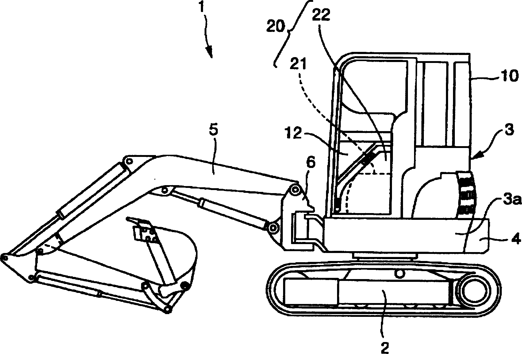
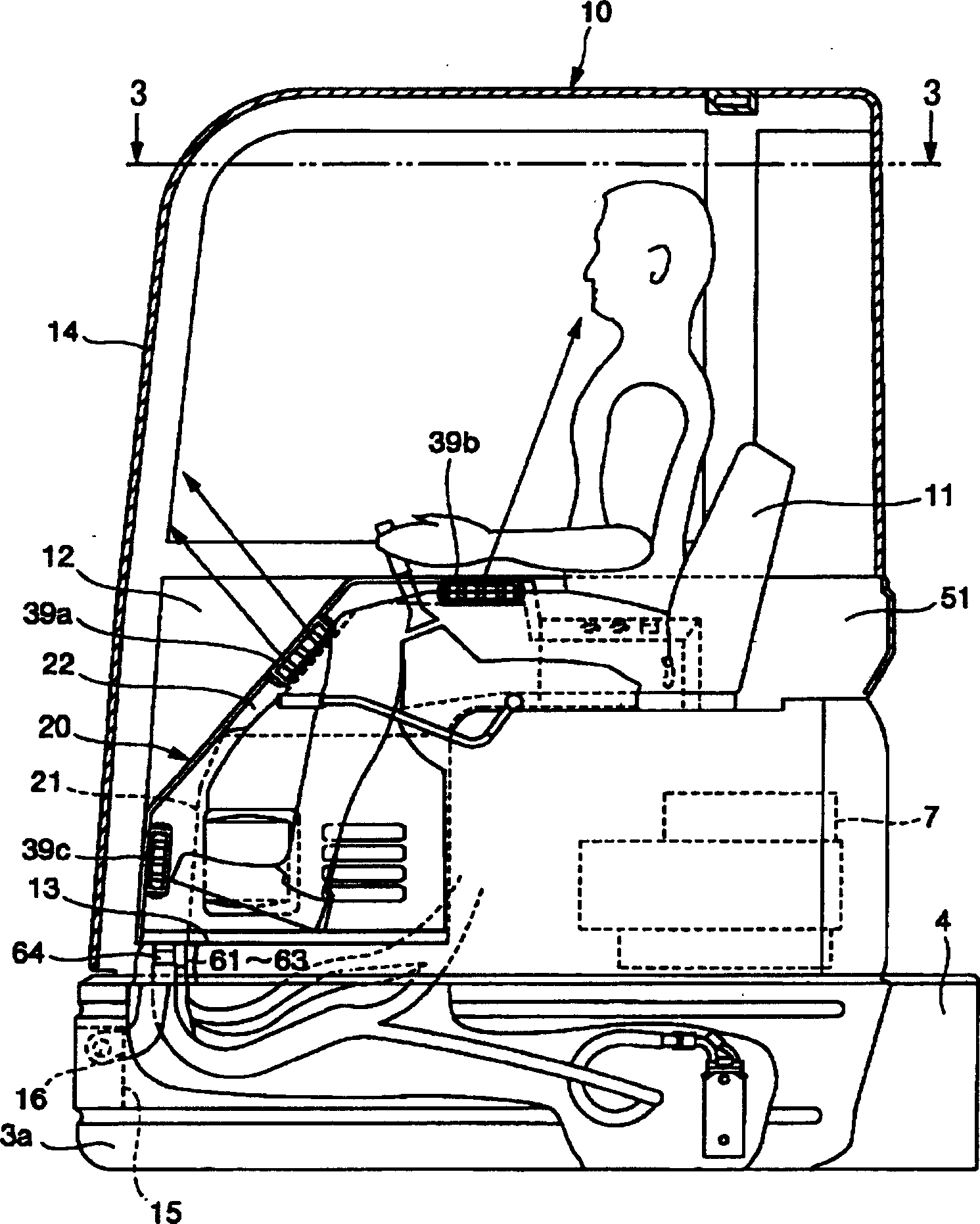
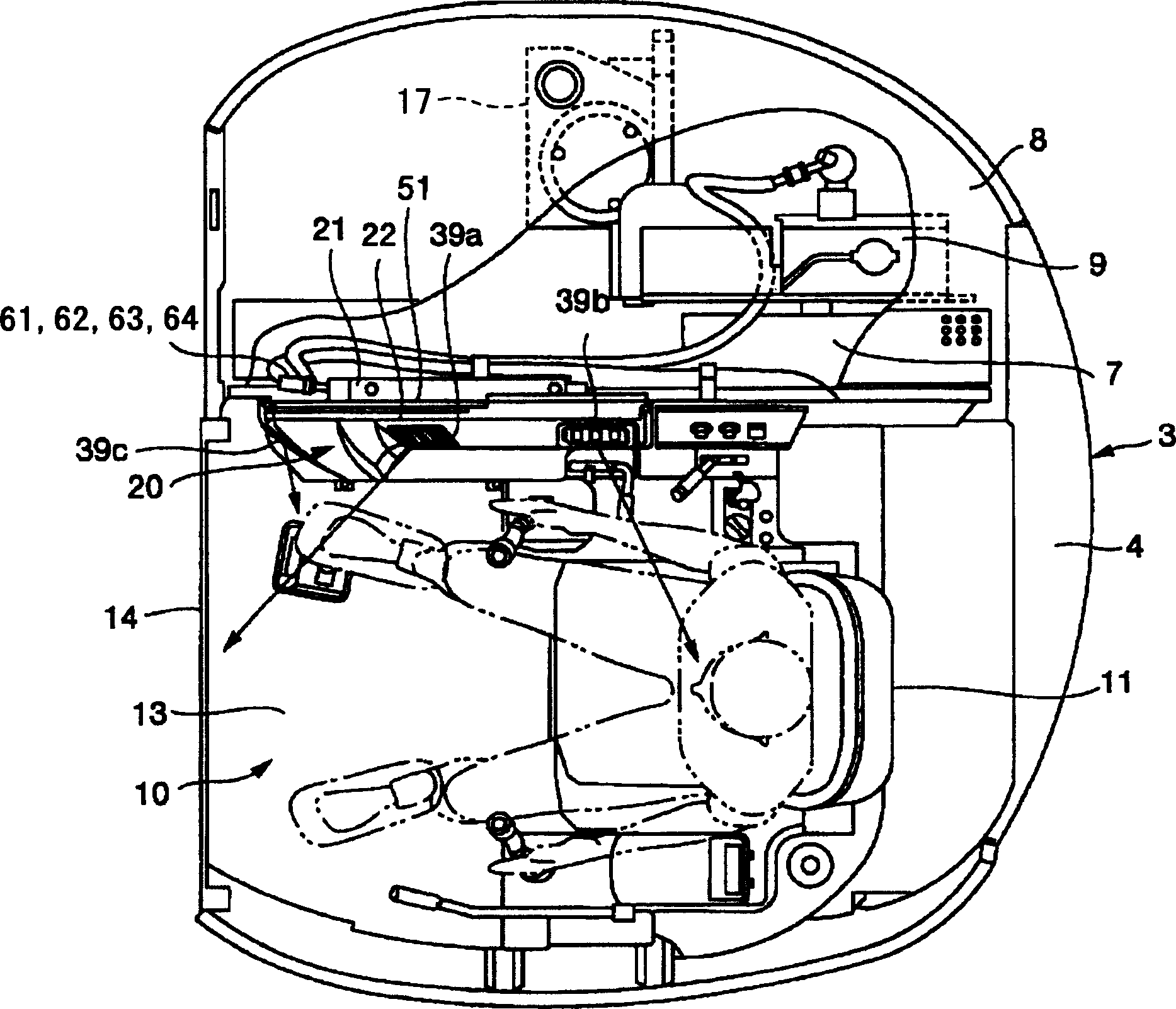
[0026] Hereinafter, preferred embodiments of the present invention will be described in detail with reference to the drawings. First, according to Figure 1~3 , to describe the outline structure of the hydraulic excavator of the ultra-small rear swing type to which the present invention is applied.

[0027] exist Figure 1~3 Among them, the hydraulic excavator 1 is equipped with an upper revolving body 3 freely rotatable on the lower traveling body 2, and a cab 10 is provided along the left end from the front central part of the revolving frame 3a provided at the lower part of the upper revolving body 3. A balance weight 4 is attached to the rear end of the frame 3a. The driver's cab 10 is swingably coupled to a bracket 15 provided at the front end of the swivel frame 3 a via horizontal pins 16 in the front and rear directions, and can be tilted at a predetermined angle around the horizontal pins 16 . Below an operator's seat 11 provided slightly rearward from the center po...


PUM


Abstract

An air conditioning apparatus for a hydraulic shovel with which a wide space in a cab can be secured and a placement operation of ducts for distributing wind to each important point in the cab is facilitated. For this purpose, in the air conditioning apparatus, an air-conditioning unit (21) is placed at a front portion of a right side in a cab (10). The air-conditioning unit (21) is mounted to a front portion of a right side wall surface (51) of the cab (10). The air-conditioning unit (21) is mounted to the right side wall surface (51) of the cab (10) to be capable of being taken in and out from an inside and an outside of the cab (10).

Description

technical field [0001] The invention relates to an air conditioner installed in the cab of a hydraulic excavator. Background technique [0002] A construction machine such as a hydraulic excavator has a cab, and the operator's seat is surrounded by a door for entering and exiting and a wall surface with windows, and a work machine operating device and a traveling operating device are installed inside the cab. In this cab, in recent years, air conditioners have been frequently installed in order to improve operability (window glass defrosters, etc.) and comfort (living) properties (air-conditioning, air conditioners). In the past, the air conditioner, for the purpose of ensuring a loose space in the cab and ensuring the visibility of the operator, for example, is installed between the operator and the rear wall of the cab (for example, refer to Japanese Patent Laying-Open No. 8-183323 No. 3 and Fig. 1), the rear wall of the cab or the floor surface under the operator's seat ...

Claims


Application Information

Patent Timeline
Patent Type & Authority Applications(China)
IPC IPC(8): E02F9/16B60H1/00
CPCB60H1/00378
Inventor 上前健志宇井邦夫
Owner KOMATSU LTD
Why Eureka
Try Eureka