Self-calibrating projection equation method for implementing stereo PIV method

A self-calibration and projection technique used in the field of projection equations

Inactive Publication Date: 2004-10-13
LAVISION
View PDF2 Cites 10 Cited by
  • Summary
  • Abstract
  • Description
  • Claims
  • Application Information

AI Technical Summary

Problems solved by technology

The disadvantage here is that the camera has to move very quickly with this method

Method used


Image

  • Self-calibrating projection equation method for implementing stereo PIV method
  • Self-calibrating projection equation method for implementing stereo PIV method
  • Self-calibrating projection equation method for implementing stereo PIV method

Examples


example 1

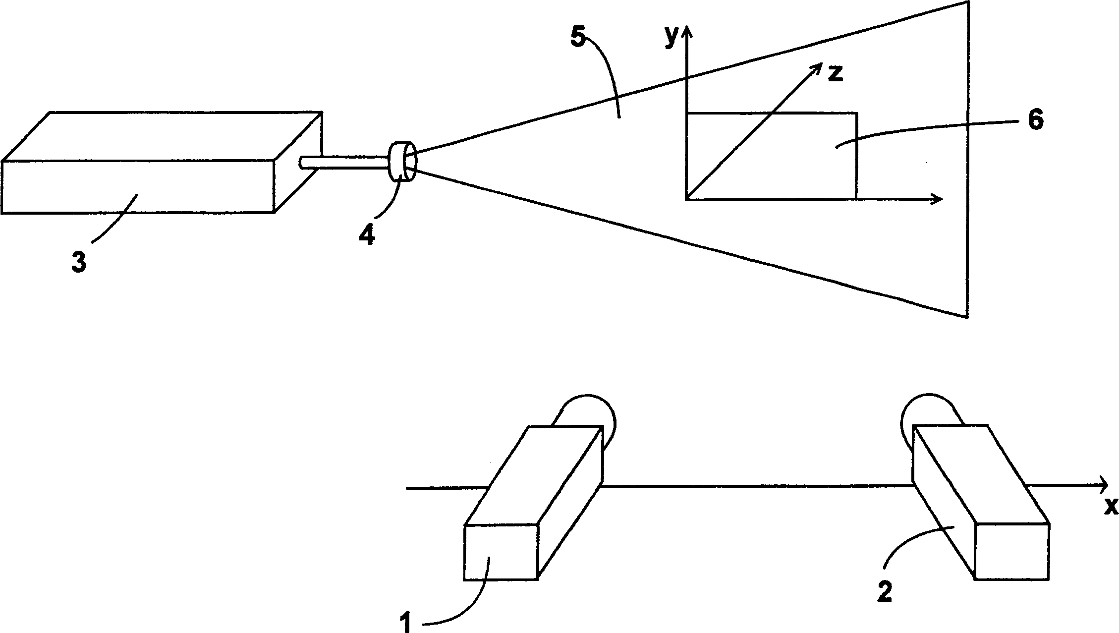
[0024] Take an ordinary camera with two cameras ( figure 1 and 2 ) based on a stereoscopic PIV-structure in which the camera can be positioned along the x-axis and aimed at the light section plane from both sides at an angle of typically 30-50°, wherein the light section plane is defined by the x-y plane with z=0. The two cameras are thus located at z=-Zcam. The principal optical axes of the cameras are coplanar and lie in a common x-y plane. Two pulsed lasers 3 generate light sections 5 at the same position with the aid of a light section optics 4 successively at short intervals, wherein two cameras record two images 6 successively at short intervals, in each image there is a laser pulse.

[0025]In this example it is assumed that a volume calibration has already been carried out independently of the actual light cross-section by, for example, simultaneous recording of a 3D calibration plate by two cameras. All internal and external image parameters relative to a coordina...

example 2

[0030] The prerequisite is the same test structure as Example 1. It is also assumed that the camera objective is angled relative to the camera plane such that the intersection / Scheimflug condition is satisfied such that all particles in the plane of the light section are in focus. Of course no pre-calibration is provided in this example, but the projection equation should be determined by the point correspondence itself. This is achieved by means of a direct approximation, in which way the missing projection parameters are determined (gefittet). Because there are many free parameters, certain assumptions must be made in order to converge to a solution. For this there are different possibilities to reduce the number of free parameters with the help of known situations:

[0031] It is assumed that, from a pre-calibration of the Scheimflug adapter performed once, it is known how the principal point (Hauptpunkt) moves as a function of the angle, or how the Scheimflug conditions ...


PUM


Abstract

A method for determining a conjugate distance equation for automatic calibration in the execution of stereo-PIV(Particle Image Velocimetry) is provided to execute calibration of stereo-PIV even in a closed space or micro-channel. A method for determining a conjugate distance equation includes ate least two cameras and a single light slit. The cameras observe a region of the light slit in different directions, and point-to-point correspondence between the cameras is determined by moving and measuring each interrogation field in camera images according to optical correlation. The conjugate equation is decided using an approximation method according to internal and external camera parameters.

Description

technical field [0001] The invention relates to a method for determining a projection equation for self-calibration for implementing a stereoscopic PIV method. Background technique [0002] First of all, it should be explained what the PIV method should be understood as. PIV is an acronym for Particle Image Velocimetry. The flow of gas or liquid in a space can be represented by means of PIV (eg DE19928698A1). In order to carry out such a PIV method, a laser or other suitable light source is first required, which produces a so-called light section in a medium, such as a gas or liquid flow, which light section is observed by at least one camera. Only one camera arranged perpendicular to the light section can determine the two velocity components in the light plane, whereas at least two cameras viewing the light section from different angles (stereo PIV) determine all three components. As already stated, the significance of the PIV method is to measure two-dimensional and th...

Claims


Application Information

Patent Timeline
Patent Type & Authority Applications(China)
IPC IPC(8): H04N17/00G01B11/00G01P5/00G01P5/20G01P5/22G01P13/00
CPCG01P5/20G01P5/22G01P5/001A23V2002/00A23V2200/218A23L11/07
Inventor B·维内克
Owner LAVISION
Why Eureka
Try Eureka