Supercharge Your Innovation With Domain-Expert AI Agents!

Method and apparatus for multi-modality imaging

An imaging device and computer technology, applied in medical science, diagnosis, computerized tomography scanner, etc., can solve problems such as image artifacts, incomplete representation of imaging objects, and unresolved imaging problems

Inactive Publication Date: 2004-10-20
GE MEDICAL SYST GLOBAL TECH CO LLC
View PDF0 Cites 34 Cited by
  • Summary
  • Abstract
  • Description
  • Claims
  • Application Information

AI Technical Summary

Problems solved by technology

For example, a CT / PET system may have a smaller CT FOV than a PET FOV, and in some scan situations, parts of the patient may protrude outside the CT detector's measurement area, which can cause image artifacts and Incomplete characterization of imaged objects
Some of the known methods that have been published aim to reduce artifacts but do not address the imaging of the portion of the patient outside the CT FOV

Method used


Image

  • Method and apparatus for multi-modality imaging
  • Method and apparatus for multi-modality imaging
  • Method and apparatus for multi-modality imaging

Examples


Embodiment Construction

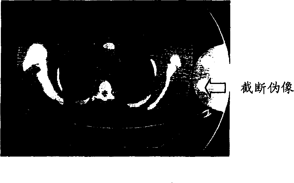
[0032] A truncation compensation method and apparatus for extended field of view in a rotating acquisition system are provided herein. As described in more detail below, in one aspect, an approach is based at least in part on properties for parallel sampling geometries for which the total amount of attenuation accumulated over all channels is independent of projection angle. The method and apparatus are explained with reference to the drawings, wherein like numerals represent like elements throughout. These drawings are for the purpose of explanation, not limitation of the present invention, and are included herein to facilitate the explanation of embodiments of the apparatus and method of the present invention.

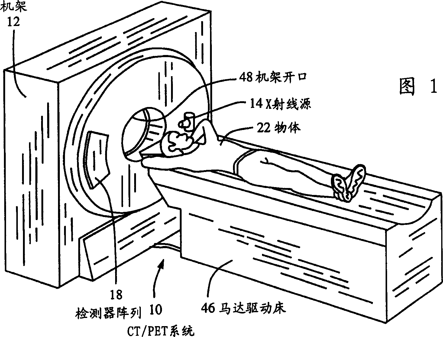
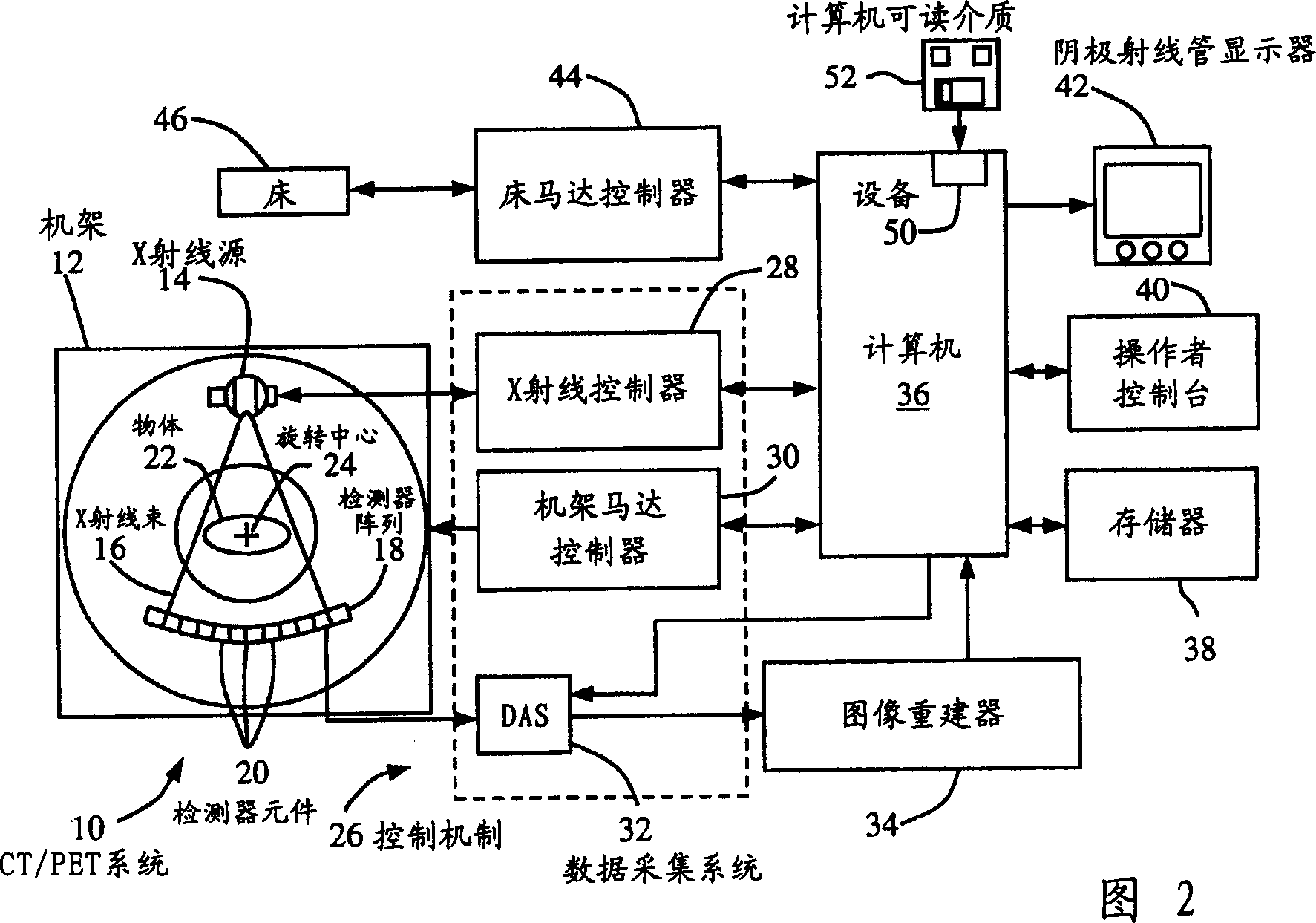
[0033]In some known CT imaging system configurations, an X-ray source projects a fan beam that is collimated and lies within an X-Y plane of a Cartesian coordinate system, commonly referred to as the "imaging plane." The X-ray beam passes through an imaged object, s...


PUM


Abstract

A method includes scanning an object in a first modality having a first field of view to obtain first modality data including fully sampled field of view data and partially sampled field of view data. The method also includes scanning the object in a second modality having a second field of view larger than the first field of view of obtain second modality data, and reconstructing an image of the object using the second modality data and the first modality partially sampled field of view data.

Description

[0001] This application claims the benefit of U.S. Provisional Application No. 60 / 416,072, filed October 4,2002. technical field [0002] The present invention relates generally to imaging systems capable of scanning objects in multiple modalities, and more particularly to multi-modal systems having modalities with different fields of view. Background technique [0003] The present invention is directed to multimodal imaging systems capable of scanning with different modalities, such as (but not limited to) Positron Emission Tomography (PET) and Computed Tomography (CT). The difference between multimodal and multimodal is that a multimodal system is used to perform scans in different modalities (such as fluorescence mode and tomosynthesis mode), while a multimodal system is used to perform scans in different modalities (such as CT and PET). It is contemplated that the benefits of the present invention arise with all multimodal imaging systems, such as (but not limited to) C...

Claims


Application Information

Patent Timeline
Patent Type & Authority Applications(China)
IPC IPC(8): A61B6/03
CPCY10S378/901A61B6/5235A61B6/032A61B6/037A61B6/027A61B6/583
Inventor 艾伯特·H·R·朗谢强查尔斯·W·斯特恩斯爱德华·H·查奥布赖恩·格里科威茨
Owner GE MEDICAL SYST GLOBAL TECH CO LLC
Features
  • R&D
  • Intellectual Property
  • Life Sciences
  • Materials
  • Tech Scout
  • Unparalleled Data Quality
  • Higher Quality Content
  • 60% Fewer Hallucinations
Learn More