Maximum power tracking control device

A technology of tracking control and maximum power, which is applied in the direction of control/regulation system, adjustment of electrical variables, instruments, etc., and can solve problems such as slow tracking speed, affecting power generation efficiency, and large voltage changes

Inactive Publication Date: 2004-10-20
ORMON CORP
View PDF1 Cites 7 Cited by
  • Summary
  • Abstract
  • Description
  • Claims
  • Application Information

AI Technical Summary

Problems solved by technology

Whereas in the case of e.g. dynamic generators, it takes a long time to get the power point to the maximum power point by the conventional hill-climbing method simply because of the slow tracking speed, which is due to the fa

Method used


Image

  • Maximum power tracking control device
  • Maximum power tracking control device
  • Maximum power tracking control device

Examples


no. 1 example

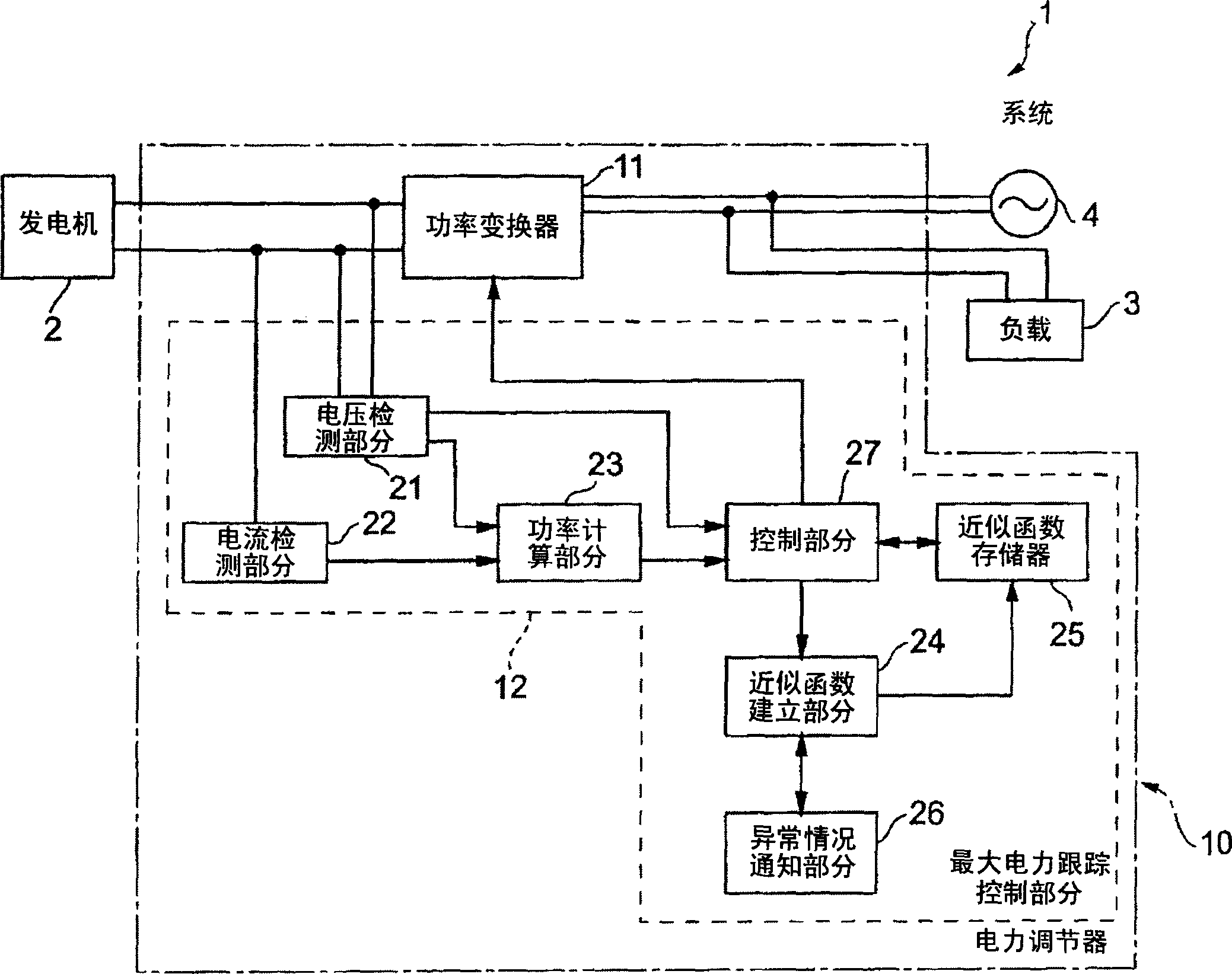
[0067] figure 1 It is a block diagram showing the internal arrangement of the discrete power generation system of the first embodiment.

[0068] Such as figure 1 The shown discrete power generation system 1 includes: a generator 2 for generating direct current; a power conditioner 10 having a power conversion function for converting the direct current generated by the generator 2 into alternating current; Consumer electronic devices driven by the converted direct current in the system; and a system 4 such as a commercial power supply that provides additional direct current to the load 3 . From this aspect, when the load 3 is powered by the power conditioner 10, when the output power of the power conditioner 10 is lower than the driving power of the load 3, in addition to being powered by the power conditioner 10, the load 3 is also powered by the system 4 powered by.

[0069] Such as figure 1 The power conditioner 10 shown includes: a power converter 11, which is used t...

no. 2 example

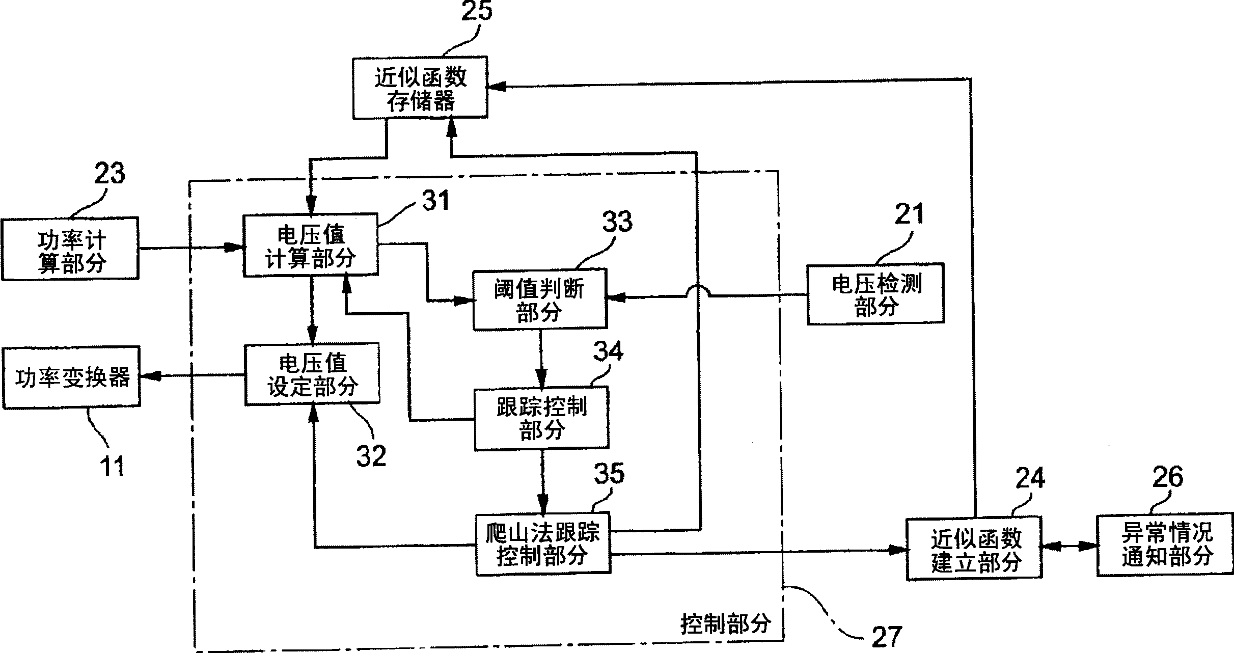
[0156] Figure 12 A block diagram is provided internally of the control section 27 of the power conditioner 10 related to the second embodiment. In this respect, those elements that are equivalent to those of the discrete power generation system 1 of the first embodiment are marked with the same reference numerals, and thus descriptions of redundant settings and operations are omitted.

[0157] Such as Figure 12 The shown control part 27 includes: a voltage value calculation part 31, a voltage value setting part 32, a threshold judgment part 33, a tracking control part 34, a mountain climbing method tracking control part 35, and also includes an approximate function correction part 36, which is passed through The error of the approximation function stored in the approximation function memory 25 is corrected using the hill climbing method of the hill climbing tracking control section 35 .


PUM


Abstract

A power conditioner 10 is provided with a maximum power follow-up control portion 12 for setting a DC operating voltage of a power converter 11, which converts output power of a power generator 2 into AC power, for making a power point corresponding to the output level of the power generator follow up with a maximum power point, and comprises an approximate function memory 25 for storing approximate functions related to the maximum power point, a follow-up control portion 34 for making the present power point reach proximate of the maximum power point on the basis of the approximate function, and a hill-climbing method follow-up control portion 35 for making the present power point reach the maximum power point by using a hill-climbing method when the present power point has reached proximate of the maximum power point.

Description

technical field [0001] The present invention relates to a maximum power tracking control device, wherein a generator for generating direct current, such as a hydroelectric generator or a wind generator, is included in a discrete power generation system, and a generator for converting the direct current of the generator into AC power, and a power conditioning device for supplying the converted AC power to the system or others (hereinafter referred to simply as "power conditioner"), the optimum power generation efficiency corresponding to the output characteristics of the generator can be Obtained internally by the power conditioner. Background technique [0002] In general, various systems such as hydroelectric power generation systems, wind power generation systems, solar power generation systems, or gas engine power generation systems are called discrete power generation systems. [0003] Such a discrete power generation system is provided as a system in which DC power gen...

Claims


Application Information

Patent Timeline
IPC IPC(8): H02M7/48G05F1/67
CPCG05F1/67
Inventor 中村耕太郎马渕雅夫细见伸一久志博信
Owner ORMON CORP
Why Eureka
Try Eureka