Magnetic head device with magnetic head sliding block and disc device using magnetic head device

A magnetic head device and technology of the magnetic head, applied in the configuration/installation of the recording head, the hydrodynamic spacing of the head, the support head, etc., can solve the problems of approaching the disk surface and ineffective magnetic elements, etc.

Active Publication Date: 2004-10-20
TDK CORPARATION
View PDF3 Cites 2 Cited by
  • Summary
  • Abstract
  • Description
  • Claims
  • Application Information

AI Technical Summary

Problems solved by technology

[0022] In order to maintain the above-mentioned ideal floating posture after the head slider is lifted, the shape of the magnetic disk facing surface on the side end surface St on the retreating side is also very important, for example, as Figure 23 In this way, a magnetic element forming surface E with a very large area is provided on the end surface St side of the withdrawal side, and the groove C is sandwiched between the positive pressure generating surface B and the magnetic element forming surface E, so that the magnetic element is formed. The positive pressure generated on the surface E is too strong. After the magnetic head slider M3 floats up, due to the positive pressure generated on the magnetic element forming surface E, the end surface St side of the withdrawing side is also easy to rise and stay away from the disk surface. As a result, , cannot effectively bring the magnetic element close to the disk surface

Method used


Image

  • Magnetic head device with magnetic head sliding block and disc device using magnetic head device
  • Magnetic head device with magnetic head sliding block and disc device using magnetic head device
  • Magnetic head device with magnetic head sliding block and disc device using magnetic head device

Examples


Embodiment

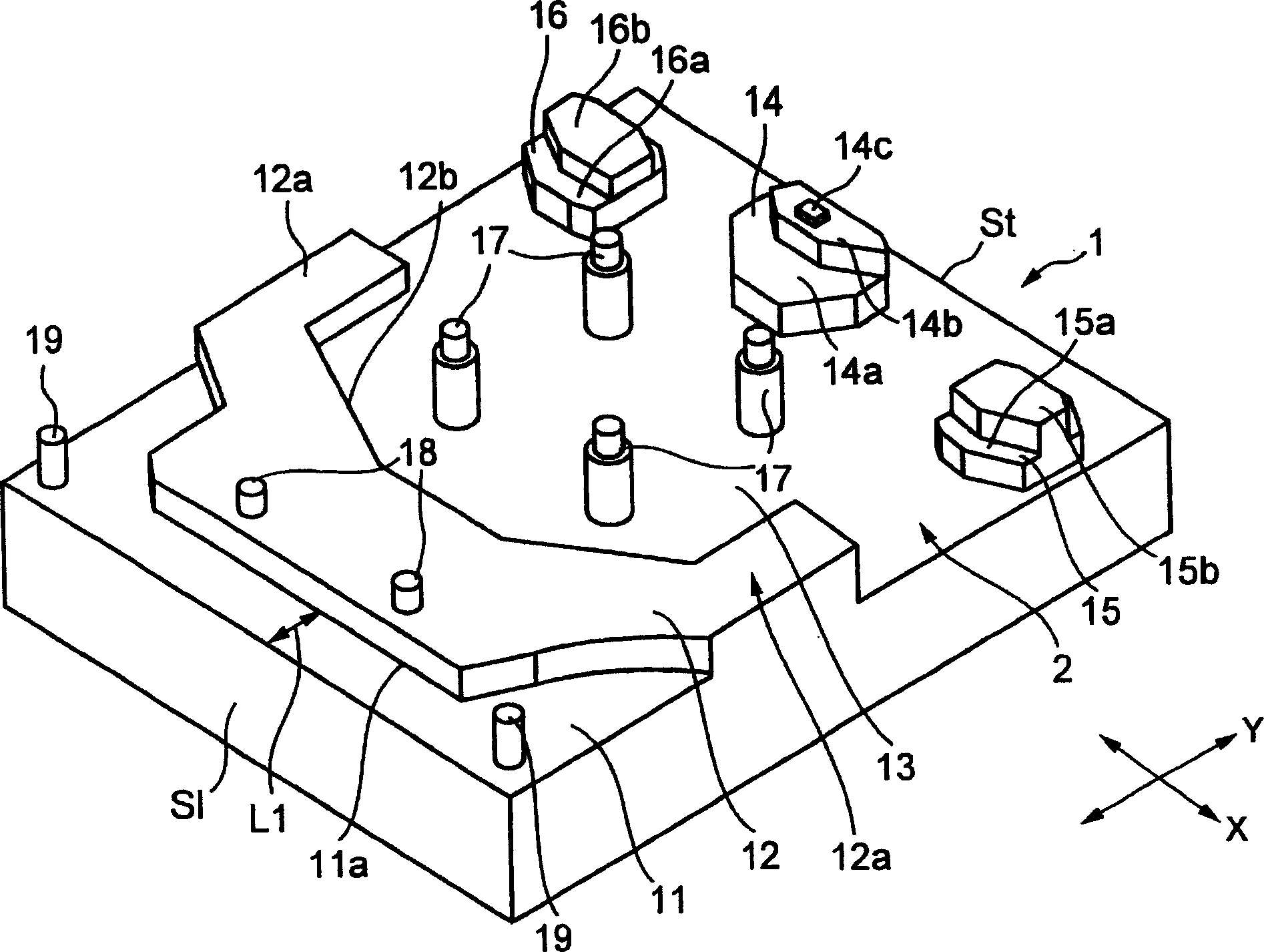
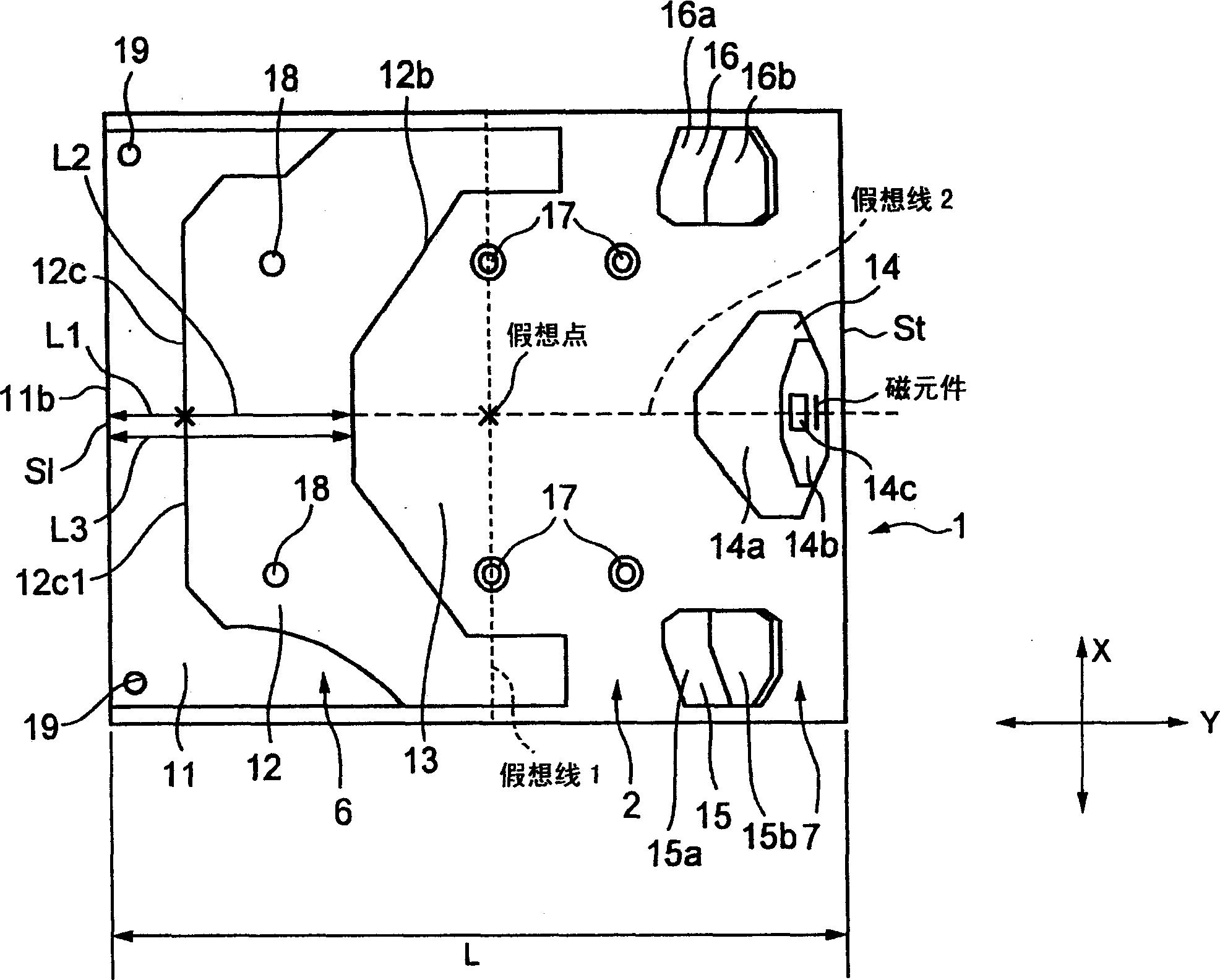
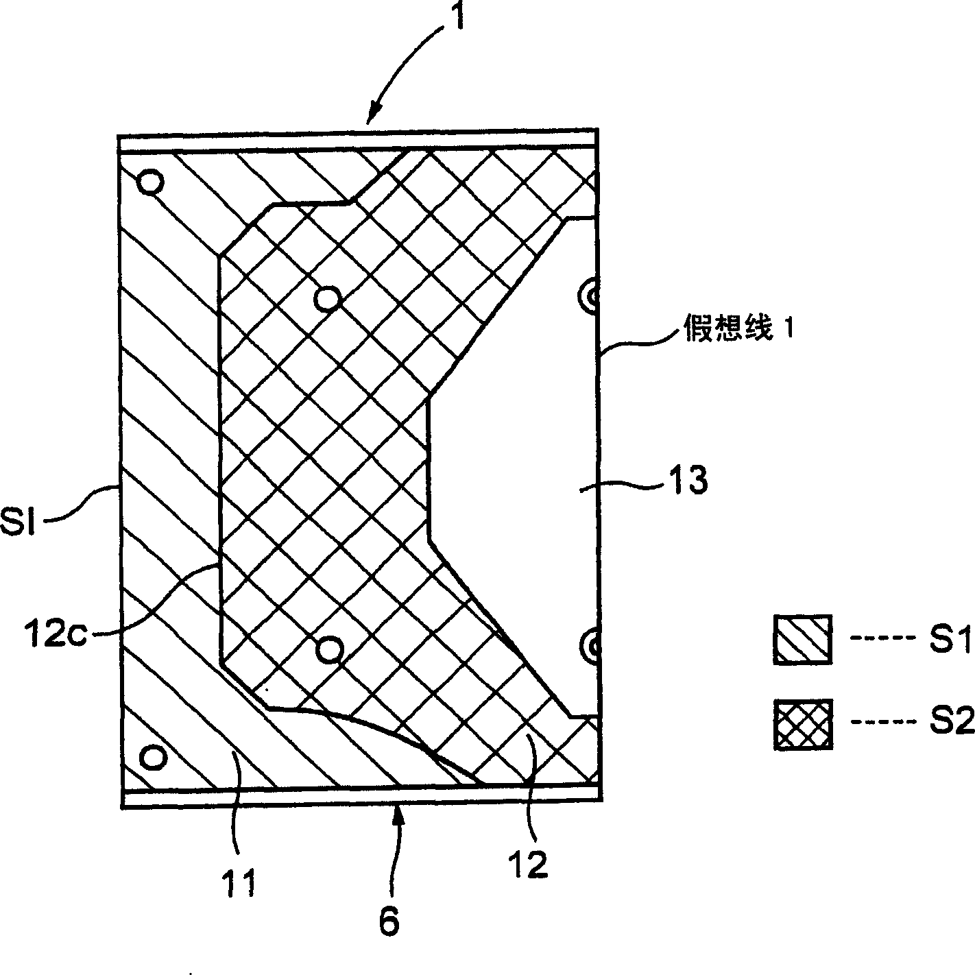
[0123] The present invention uses Figure 11 The shown magnetic head slider 30 was subjected to the following simulation experiments. Figure 11 The illustrated magnetic head slider 30 is a plan view with the magnetic disk facing surface 2 facing upward. marked with figure 1 and figure 2 The surfaces of the magnetic head sliders 1 shown with the same symbols indicate the same surfaces.

[0124] Figure 11 Shown head slider 30 with figure 2 The head slider 1 shown is very approximate. In particular, the shapes of the virtual line 1 drawn from the virtual point in the width direction (X direction in the figure) and the stepped surface 11, positive pressure generating surface 12, and groove 13 formed in the front end region 6 between the introduction side end surfaces S1 are figure 2 and Figure 11 are the same in both.


PUM


Abstract

A magnetic head apparatus including a magnetic head slider having an overall front half region area (S) and a step surface area (S1) and a positive-pressure generating surface area (S2) both in the front half region, such that the area ratio S1 / S is about 0.180 to about 0.232 and the area ratio S1 / S2 is about 0.30 to about 0.47. With this arrangement a difference in pitch angles of the magnetic head slider at the moment when it is just levitated and during levitation is large, and a variation of the pitch angle due to a pressure change is small, thereby preventing damage to a magnetic element within the magnetic head slider while achieving a stable levitation attitude of the magnetic head slider.

Description

technical field [0001] The present invention relates to a magnetic head device equipped with a magnetic head slider equipped with a magnetic element for recording and / or reproducing on a magnetic disk and a magnetic disk device using the same, and particularly relates to increasing the floating time of the magnetic head slider from the magnetic disk and The difference in the inclination angle after floating can reduce the change of the inclination angle caused by the change of air pressure at the same time, so that the damage to the magnetic element can be prevented and the magnetic head device and the magnetic disk device using it can be stabilized in the floating posture of the magnetic head slider . Background technique [0002] Figure 21 It is a plan view schematically showing the magnetic disk facing surface of the magnetic head slider described in Patent Document 1 shown below, Figure 22 It is a plan view schematically showing the magnetic disk facing surface of the...

Claims


Application Information

Patent Timeline
Patent Type & Authority Applications(China)
IPC IPC(8): G11B5/60G11B21/21
CPCG11B5/6005
Inventor 上田淳生石原弘久近藤康之森川谕中嶋启视
Owner TDK CORPARATION
Why Eureka
Try Eureka