Method for preparing laser label on reflective materials

A processing method and technology for reflective materials, applied in laser welding equipment, metal processing equipment, optics, etc., can solve the problems of destroying the reflective material matrix, low difficulty, inconvenience, etc., and achieve the effect of good optical effect and high imitation difficulty.

Inactive Publication Date: 2004-10-27
MERIT CO LTD
View PDF2 Cites 2 Cited by
  • Summary
  • Abstract
  • Description
  • Claims
  • Application Information

AI Technical Summary

Problems solved by technology

And this method, to put it bluntly, is the same as etching a logo on the surface of a dish, without any special optical effect
Although the above-mentioned second prior art has a certain degree of optical effect, it can only be used for spherical reflectors and cannot be used for polyhedral reflectors.
Moreover, it is very inconvenient to process the bottom of the spherical reflector of the ready-made opaque matrix reflective material into a plane, which will destroy the original matrix of the reflective material.
Therefore, this method cannot be adopted by small and medium-sized manufacturers who purchase ready-made reflective materials.
More importantly, this method does not make full use of the structural characteristics of the reflective material, so the difficulty required for imitation is not high.

Method used


Image

  • Method for preparing laser label on reflective materials
  • Method for preparing laser label on reflective materials
  • Method for preparing laser label on reflective materials

Examples


Embodiment Construction

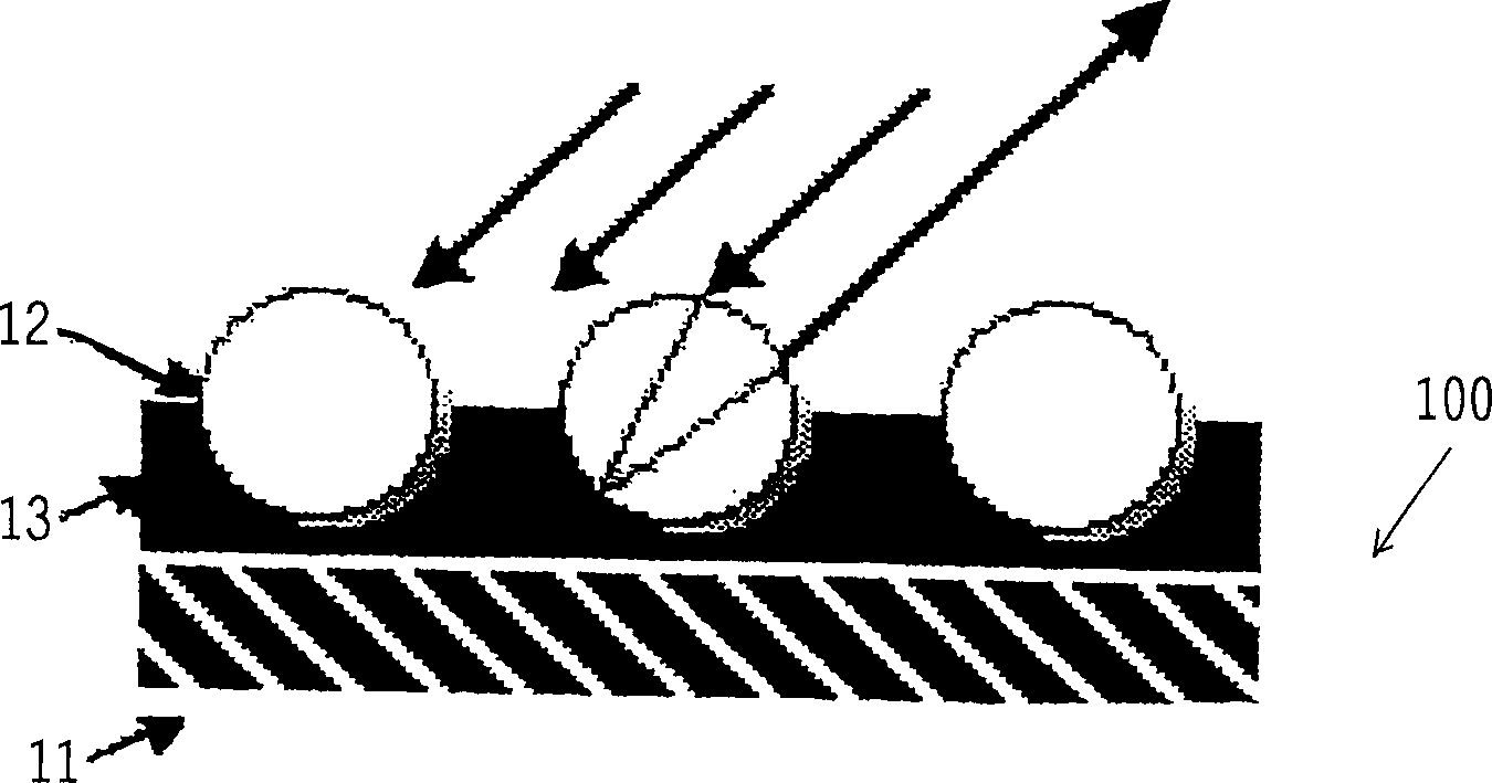
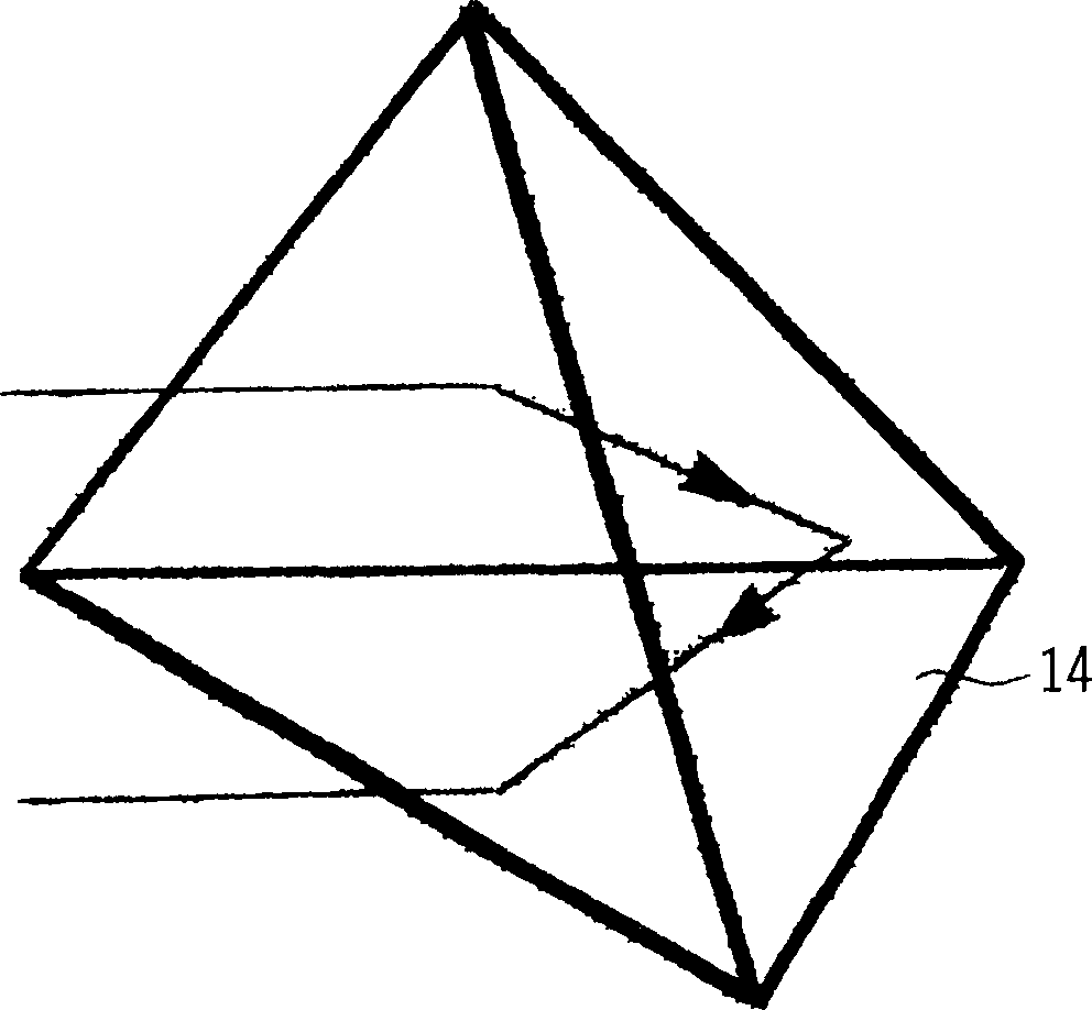
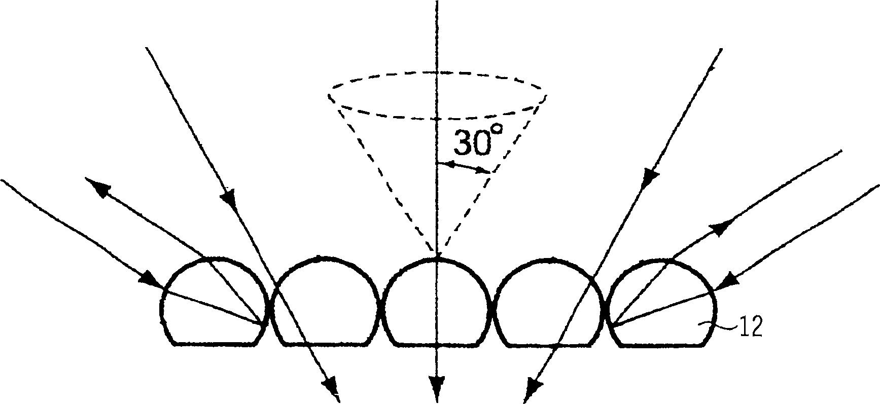
[0030] Figure 4 It is a schematic diagram when the laser beam burns the mark on the reflective material according to the method of the present invention. Figure 4 Although it is a spherical reflector 12 in the picture, it is exactly the same for the effect of the reflector 14 of polyhedron shape. The laser beam used can irradiate at least an area larger than a spherical surface of the reflector. Figure 4 The processing laser beam of the present invention shown in is not irradiated to the reflector 12 along the direction of the bottom of the vertical reflector, but irradiates the reflector 12 with a certain angle, that is, any angle of incidence between 10° and 80° The first incident surface on the upper part makes the surface produce tiny gasification hairs, so that the incident light is scattered or refracted in multiple directions, so that it will not be reflected in the incident direction; when viewed along the direction of this incident angle, the gas The hairy surfac...


PUM


Abstract

A method for using laser to prepare multiple image on a single laser marker on reflective material is disclosed. Said multiple images can be seam from different directions. Said method features that a laser beam with an incident angle is used to selectively roughen one surface of each reflector group and the laser beam with another incident angle is used to selectively roughen their another surface to form the dark dots and bright dots due to different reflectivities. Many dark dots and bright dots can form the images.

Description

technical field [0001] The invention relates to a method for processing visible marks on reflective materials with laser, especially a method for processing multiple images on the same laser mark but only observed from different angles on reflective materials of basic objects. Background technique [0002] In addition to having a certain visual beauty and a certain degree of durability, the marking of a product (Marking, also known as a label) must be able to prevent it from being copied by others. Therefore, some brand-name products currently use laser markings that are difficult to make, that is, patterns and characters are made with lasers on off-the-shelf commercially available reflective materials. In order to withstand multiple washings together with the clothing, laser markings for clothing generally use reflective materials such as cloth base or plastic film base. [0003] Depend on figure 1 It can be seen that the general commercially available reflective material...

Claims


Application Information

Patent Timeline
Patent Type & Authority Applications(China)
IPC IPC(8): B23K26/00B23K26/36B41M3/14B41M5/24G02B5/00
CPCB41M3/148B41M5/24
Inventor 叶锦福
Owner MERIT CO LTD
Why Eureka
Try Eureka