Timing and data recovery circuit

A technology for recovering circuits and data, applied in electrical digital data processing, instruments, etc., can solve the problem of high power consumption of D-type flip-flops, and achieve the effect of low power and small volume

Active Publication Date: 2004-10-27
VIA TECH INC
View PDF0 Cites 7 Cited by
  • Summary
  • Abstract
  • Description
  • Claims
  • Application Information

AI Technical Summary

Problems solved by technology

However, in order to determine the input data DATA as correctly as possible in , the data sampler 26 in the CDR20 must include a sufficient number of D-type flip-flops (or any implementation with a phase delay

Method used


Image

  • Timing and data recovery circuit
  • Timing and data recovery circuit
  • Timing and data recovery circuit

Examples


Example Embodiment

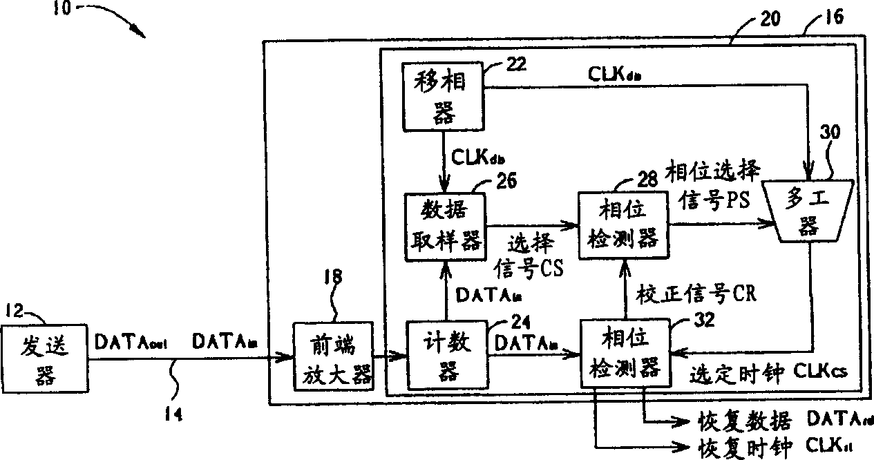
[0027] The phase shifter of the CDR in the preferred embodiment of the present invention generates M separate clock signals CLK less than the conventional number dis , And then separate the clock signal CLK from any two adjacent dis ,Insert at least one inserted clock signal CLK int , Together with the two adjacent separated clock signals CLK dis To form a set of clock signals, and then select one from the set of clock signals that is more synchronized with an input data DATA in Selected clock signal CLK cs . Since at least one plug-in clock signal CLK is guided in the plug-in manner int Only a set of common circuits can be realized, so there is no need to implement a data sampler with a large number of D-type flip-flops as usual, so the number of D-type flip-flops and the volume occupied by them can be greatly reduced, and the manufacturing cost is greatly reduced.

[0028] See Figure 4 It is a functional block diagram of a CDR in a preferred embodiment of the present invention....


PUM


Abstract

A recovery clock signal is generated from an input data and relevant reference clock signal. The circuit include following parts: phase shifter generates M pieces of separated clock signals with different phases based on reference clock signal; a data sampler generates a selection signal from input data and M pieces of separated clock signals; selector of original phase outputs two adjacent separated clock signals and a insertion clock signal based on the selection signal; multiplexer selects one selected clock signal from the said two adjacent separated clock signals and the insertion clock signal, a phase detector and a leading phase selector.

Description

technical field [0001] The present invention relates to a serial data communication system (serial data communications), in particular to a clock and data recovery circuit (CDR) applied in the serial data communication system. Background technique [0002] Compared with the parallel data transmission system (paraLLel data communications), the serial data transmission system has the advantages of small size and long transmission distance. Although the data transmission rate of the serial data transmission system is slower than that of the parallel data transmission system, in recent years, some serial data transmission devices such as USB1.1 and USB2.0 have made up for the shortcomings of the slow transmission rate. Among them, the data transmission rate of USB1.1 can reach 12Mbps, while the data transmission rate of USB2.0 can be as high as 480Mbps. [0003] see figure 1 It is a schematic diagram of a conventional serial data transmission system. The serial data transmiss...

Claims


Application Information

Patent Timeline
IPC IPC(8): G06F13/00G06F13/20
Inventor 吴清延
Owner VIA TECH INC
Why Eureka
Try Eureka