Eccenterfixed on vibrating motor

A technology of vibrating motors and motors, applied in the direction of electric components, controlling mechanical energy, electrical components, etc., can solve problems such as weak riveting strength

Inactive Publication Date: 2004-10-27
SHICOH MOTOR (SHANGHAI) CO LTD
View PDF1 Cites 2 Cited by
  • Summary
  • Abstract
  • Description
  • Claims
  • Application Information

AI Technical Summary

Problems solved by technology

Also because the standing part 107 presses the rotating shaft 105 through two points of force on both sides, this kind of copper dist

Method used


Image

  • Eccenterfixed on vibrating motor
  • Eccenterfixed on vibrating motor
  • Eccenterfixed on vibrating motor

Examples


Embodiment Construction

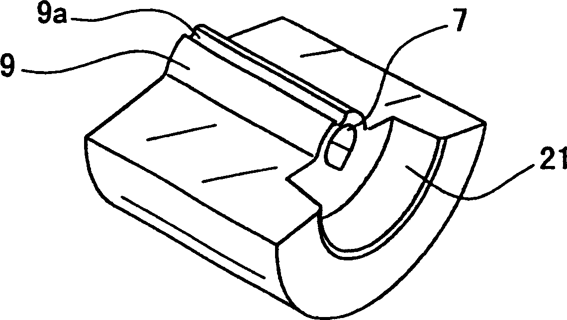
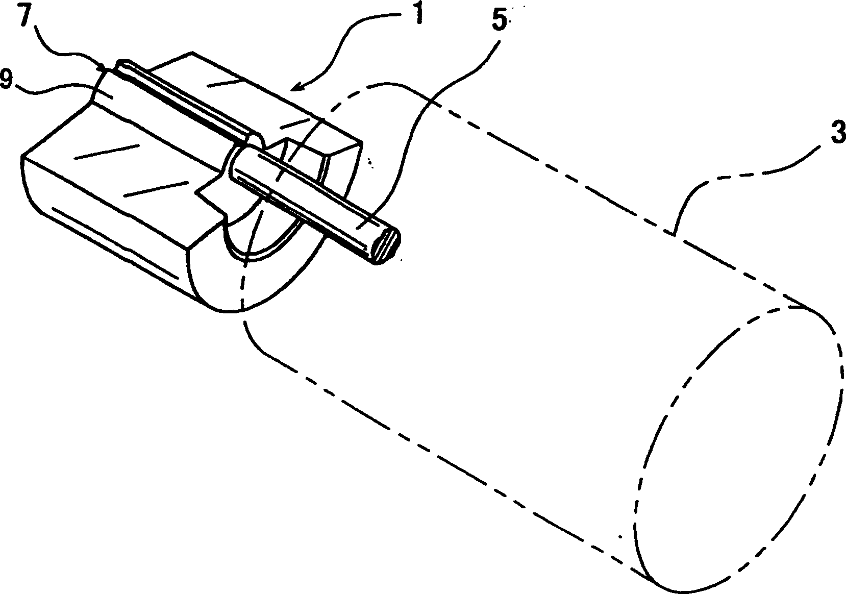
[0020] Please see first figure 2 and combine figure 1 Shown, the present invention divides copper 1 and is used for fixing vibrating motor 3 ( figure 2 Shown with double dotted lines), the rotating shaft 5 of the vibrating motor 3 is fixed on the copper, and when the motor 3 rotates, the copper 1 vibrates. Vibration motors 3 of this type are commonly used in such occasions as pagers and other similar occasions in which users are notified by vibrating when a call occurs.

[0021] In this embodiment, as seen from the axial direction (horizontal direction) of the rotating shaft 5 of the vibration motor 3, it is slightly semi-cylindrical. The material of the sub-copper 1 is not particularly limited, but it is generally better to use a material with a larger specific gravity and better extensibility. It is usually composed of tungsten alloys such as W-Ni-Fe, W-Ni-Cu, W-Mo-Ni-Fe and other series.

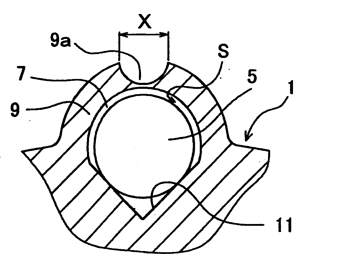
[0022] Sub-copper 1 structure such as image 3 As shown, it has a through hol...


PUM


Abstract

Through hole is made along axial of eccenter. There is a ridgy wall part at upper part of the through hole or a notch is setup at center on outer edge of wall part. Inner edge face of the wall part is bent as circular arc face, and two crossed flatten faces are positioned at lower part of the through hole. Axis of rotation of motor is inserted into the through hole of eccenter, and riveting the wall part fixes the eccenter on the motor. Since the said notch is a weak part, when being riveted, the wall part is pressed down to the axis of rotation. When being riveted the wall part will not be chapped since inner edge face is a circular arc face bent along axis of rotation. Wall part of the invented eccenter is not easy to be damaged and riveting intensity is increased.

Description

technical field [0001] The invention relates to the peripheral equipment of the vibration motor in the pager, and more specifically refers to a copper divider fixed on the vibration motor. Background technique [0002] Vibration motors are usually used in similar occasions such as pagers to notify the other party through vibration when a call occurs. Of course, the copper (also called vibrator) used to fix the motor is indispensable. Japanese Patent No. 2518781 (Please specify whether the patent is a Japanese patent) has disclosed this structure of copper, such as Figure 7 As shown, a groove 103 for inserting the rotating shaft 105 from the vertical direction is formed in the copper part 101 . On the top of the groove 103 there are raised rising portions 107, which are arranged facing each other. The inner surface of the standing portion 107 is straight, and the outer surface is tapered. When it is necessary to rivet the motor rotating shaft 105 with the raised portion 10...

Claims


Application Information

Patent Timeline
IPC IPC(8): H02K7/065
Inventor 白木学陆龙斌
Owner SHICOH MOTOR (SHANGHAI) CO LTD
Why Eureka
Try Eureka