Optical monitor module

A monitor and optical technology, applied in the field of optical monitor components, can solve the problems of increasing light loss, large space, occupation, etc.

Inactive Publication Date: 2004-11-03
JAPAN AVIATION ELECTRONICS IND LTD
View PDF1 Cites 5 Cited by
  • Summary
  • Abstract
  • Description
  • Claims
  • Application Information

AI Technical Summary

Problems solved by technology

This component structure does not produce losses due to passing through the optical waveguide, but due to the distance between the optical fiber and the beam splitter, the beam is diverged (ie, the beam diameter increases), which will increase the loss of light
In addition, the two fibers are basically at right angles to each other, which also takes up a lot of space

Method used


Image

  • Optical monitor module
  • Optical monitor module
  • Optical monitor module

Examples


Embodiment Construction

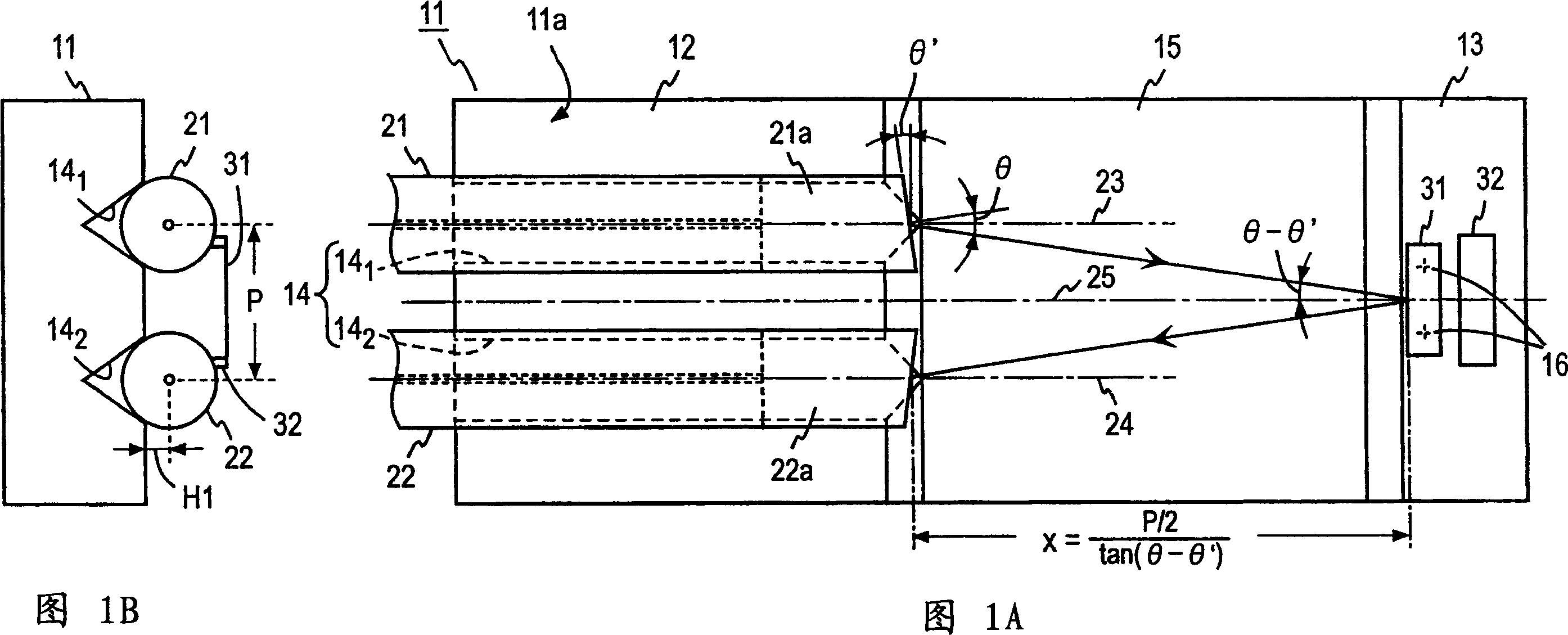
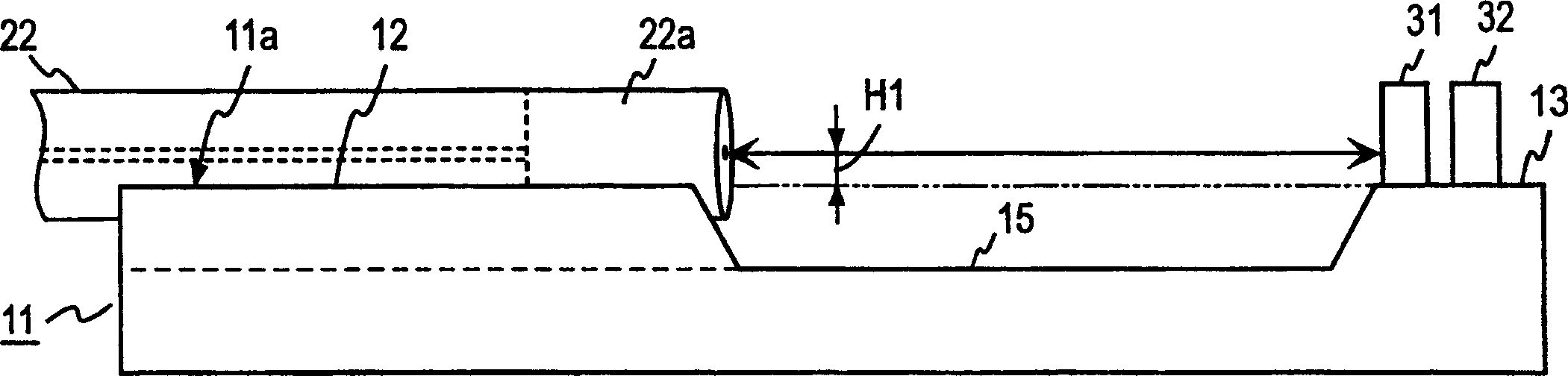
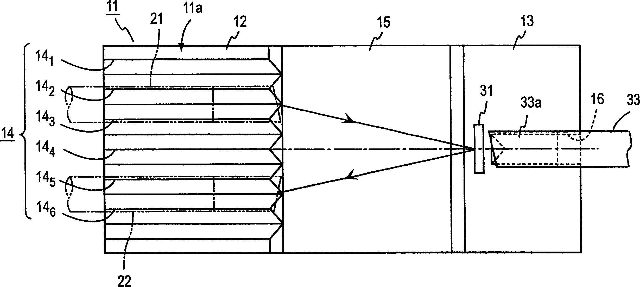
[0013] Referring first to FIG. 1, an embodiment of the present invention will be described. An optical fiber mounting portion 12 and a component mounting portion 13 are formed on a surface 11a of the base 11, the optical fiber mounting portion 12 has a positioning structure 14 for positioning a plurality of optical fibers, and is used to position a plurality of optical fibers so that they are in a parallel relationship and extend in a direction in which the optical fiber mounting portion 12 and the component mounting portion 13 are arranged opposite to each other. The positioning structure 14 positions the optical fibers in a direction perpendicular to the surface 11 a of the substrate 11 and in a direction in which the optical fibers are arranged side by side. The optical fibers 21 and 22 whose ends are positioned by the positioning structure 14 are mounted on the fiber mounting portion 12 . A splitter or filter 31 is mounted on the component mounting portion 13 at an interm...


PUM


Abstract

In one half portion of one surface of a substrate there are formed in parallel V-grooves of the same depth, in which optical fibers and are disposed and positioned with their axes held at a height H1 with respect to the surface. The optical fibers and have lens portions formed integrally therewith at one end, and the end faces of the lens portions are tilted at an angle theta' from their axes. A beam splitter is mounted on the substrate on a center line between elongations of the optical fibers, and light emitted from the lens portion propagates through space and is launched in focused form into the beam splitter, and a portion of the incident light is reflected, which propagates space and is launched in focused form into the lens portion and propagates through the optical fiber. The light having passed through the beam splitter is launched into a light receiving element. By monitoring an electrical signal that is output from the light receiving element, it is possible to monitor the light propagating through the optical fiber.

Description

technical field [0001] This invention relates to optical monitor assemblies which direct a portion of light emitted from one optical fiber into another optical fiber for transmission therefrom to a monitoring component. Background technique [0002] In a conventional optical monitor module, light emitted from an optical fiber is incident on an optical waveguide on an optical waveguide substrate having optical splitting lines formed thereon, and light split by the optical splitting lines is transmitted from The optical waveguide substrate emits for incidence into a surveillance zone. This prior art is disclosed in, for example, Japanese Patent Application Laid-Open Nos. 2001-358362 and 347665 / 94. [0003] Using this conventional optical monitor assembly to monitor the light separated by the optical waveguide splitting line formed on the optical waveguide substrate, due to the transmission loss of the optical waveguide, it is necessary to split relatively high power light for...

Claims


Application Information

Patent Timeline
Patent Type & Authority Applications(China)
IPC IPC(8): G02B6/26G02B6/28G02B6/32G02B6/34G02B6/36G02B6/42
CPCG02B6/3652G02B6/327G02B6/3636G02B6/29361G02B6/4214G02B6/4206G02B6/2817G02B6/4215G02B6/262
Inventor 森惠一
Owner JAPAN AVIATION ELECTRONICS IND LTD
Why Eureka
Try Eureka