Three-dimensional image display device, portable terminal device, and lenticular lens
A technology of image display and display panel, applied in the direction of lens, image communication, instrument, etc., can solve the problems of lower display quality, glare, low visibility, etc., and achieve the effect of improving display quality
Active Publication Date: 2004-11-03
GOLD CHARM LTD
0 Cites 5 Cited by
AI-Extracted Technical Summary
Problems solved by technology
[0006] The above-mentioned parallax barrier method, when originally invented, had the following problem: since the parallax barrier is arranged between the pixels and the eyes, it becomes an eyesore and results in low visibility
In partic...
Method used
[0050] As noted above, the striped pattern is most clearly seen when the light and dark portions of the strip are equal in width and each width is (1/2) the lens pitch. Therefore, in the present invention, the lens pitch L of the cylindrical lenses 3 is set to be equal to or less than twice the product of the optimal observation distance OD and the tangent of the angle of 1 minute. Like this, because the viewer can't identify in the three-dimensional image, because the external light is reflected at the surface place of the double-sided lens 2, the belt-shaped pattern that produces, so the display quality of the three-dimensional image that the viewer sees is compared with the existing three-dimensional image. Image display equipment ...
Abstract
A three-dimensional image display device is provided with a liquid crystal display panel, where a plurality of pixels for the right eye displaying an image for the right eye and a plurality of pixels for the left eye displaying an image for the left eye are arrayed, and a lenticular lens that is arranged on a side of the liquid crystal display panel, which faces a viewer, and whose surface facing the liquid crystal display panel is flat and surface facing the viewer has a plurality of hog-backed cylindrical lenses formed thereon so as to be parallel with each other, in which the lens pitch of the cylindrical lenses of the lenticular lens is set to 0.2 mm or less.
Application Domain
Steroscopic systemsNon-linear optics +1
Technology Topic
Liquid-crystal displayLenticular lens +6
Image
Examples
- Experimental program(1)
Example Embodiment
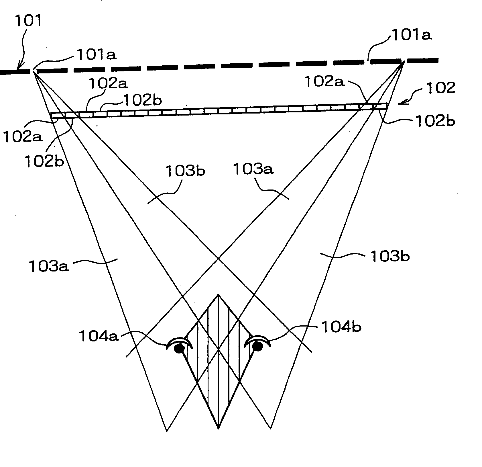
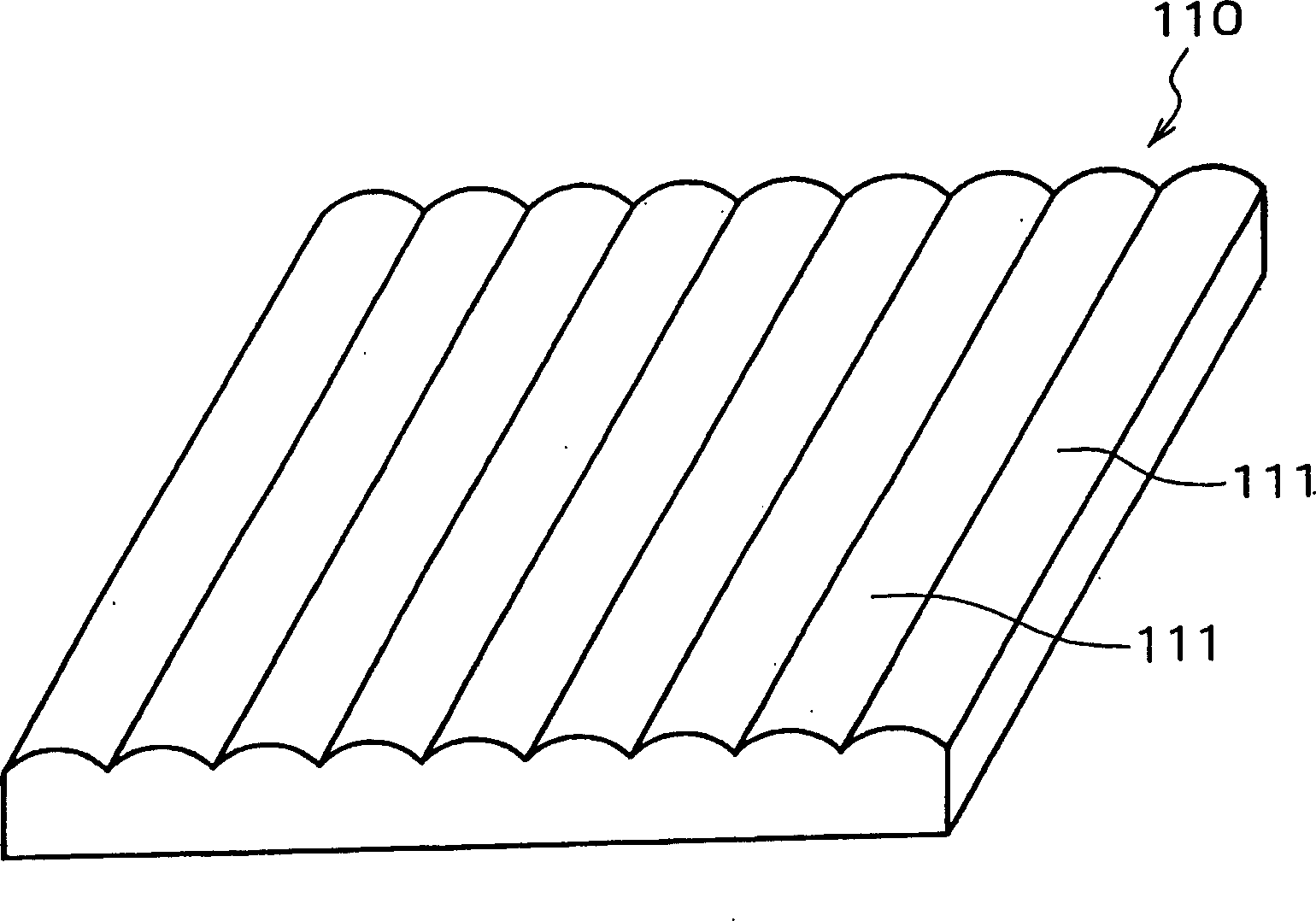
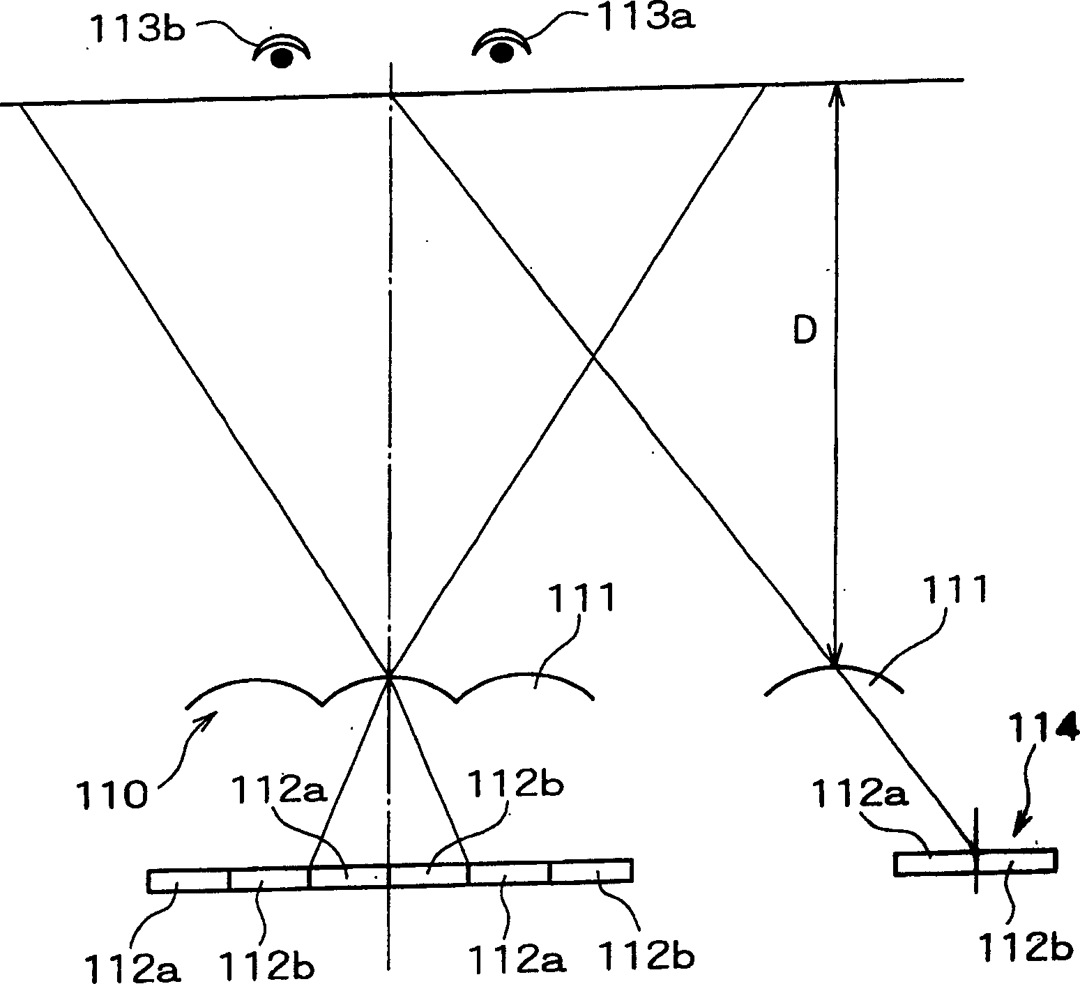
[0043] Because in the existing three-dimensional image display device of the double-sided lens method, the band-shaped pattern on the bottom frame is seen and covered on the display image, so that the quality of the display image recognized by the viewer is reduced and therefore The band-shaped pattern becomes a dazzling object in image observation. Therefore, the inventors of the present invention devoted themselves to the research on the lens pitch L of the cylindrical lens of the double-sided lens and the visibility of the band patterns appearing on the three-dimensional image, and found that when external light is reflected on the lens surface When you see a striped pattern.
[0044] The total width of the bright part and the dark part of the striped pattern is equal to the lens pitch L of the cylindrical lens, and the width of each bright part and dark part varies according to the characteristics of external light. Figure 5A It is a standard view showing the light reflection on the lens surface when the external light is divergent light, and Figure 5B It is a standard view showing the light reflection on the lens surface when the external light is parallel light. Such as Figure 5A As shown, when the external light is divergent light, the external light 6a from multiple directions is reflected on the surface of the double-sided lens 2, so that the reflected light incident on the viewer 5 does not depend on the surface of the double-sided lens 2 s position.
[0045] On the other hand, such as Figure 5B As shown, when the external light 6a is parallel light, the reflection direction is different according to the position at the surface of the double-sided lens 2, and the light reflected at a specific position is incident on the viewer 5 and the light emitted at other positions is not Will be incident on the viewer 5. In this way, the viewer recognizes the bright and dark band patterns corresponding to the shape of the lens surface in the three-dimensional image. In fact, the flow distribution characteristics of external light depend on the environment in which the lens is used. For example, light is parallel light under direct gaze and divergent light in an indirectly illuminated room. In addition, it is known that light in the vicinity of direct fluorescent irradiation has a characteristic that is a mixture of parallel light and divergent light. The flow distribution characteristics of the external light are different according to the environment; each width of the bright part and the dark part of each strip pattern appearing on the three-dimensional image depends on the environment in which the lens is used.
[0046] In addition, as described above, the total width of the bright part and the dark part is equal to the lens pitch L of the cylindrical lens 3 of the double-sided lens 2, and is usually fixed. For this reason, when the width of the bright portion increases due to the flow distribution characteristics of the external light 6a, the width of the dark portion decreases, and in contrast, when the width of the dark portion increases, the width of the bright portion decreases. In this case, because the reduced width part is difficult to recognize, it will not be recognized as a strip pattern. Therefore, when the bright part and the dark part have the same width, that is, when each of the bright part and the dark part has the (1/2) width of the lens pitch, the band-shaped pattern can be seen most clearly . In order to prevent the viewer from recognizing the band-shaped pattern, it is necessary to set the width of the bright part or the width of the dark part to be greater than or equal to the resolution of the viewer's vision. The relationship between the eyesight of the viewer and the minimum viewing angle that the viewer can recognize is given by Expression 3 below.
[0047] (Expression 3)
[0048] Vision = 1/minimum viewing angle (minutes)
[0049] For example, assuming that the visual acuity of the viewer is a normal visual acuity of 1.0, according to Expression 3, the minimum viewing angle of the viewer is 1 point. In addition, when a display panel is used, a plurality of pixel parts including pixels for displaying an image for the left eye and pixels for displaying an image for the right eye are periodically arranged, and when the viewer can recognize The distance between the longest line segment among the multiple line segments in the three-dimensional visible range of the three-dimensional image and the surface of the optical unit is the best distance for the viewer to recognize the three-dimensional image, that is, the best observation When the distance OD (mm), and the best observation distance OD is less than or equal to 350mm, the viewer’s resolution is equal to the product of the best observation distance OD and the tangent of the angle of 1 minute, wherein the multiple line segments are parallel to the connection display for The pixels of the left-eye image and the line segment showing the pixels for the right-eye image. Therefore, when the optimal observation distance OD is less than or equal to 350 mm, by setting the width of the bright part or the width of the dark part to be less than or equal to this value, the viewer cannot recognize the strip pattern.
[0050]As mentioned above, when the widths of the bright part and the dark part of the belt are equal and each width is (1/2) of the lens pitch, the belt-shaped pattern can be seen most clearly. Therefore, in the present invention, the lens pitch L of the cylindrical lens 3 is set to be less than or equal to twice the product of the optimal observation distance OD and the tangent of the angle of 1 minute. In this way, because the viewer cannot recognize the band-shaped pattern in the three-dimensional image due to the reflection of external light on the surface of the double-sided lens 2, the display quality of the three-dimensional image seen by the viewer is compared with the existing three-dimensional image. The image display equipment has been improved.
[0051] Hereinafter, a three-dimensional image display device according to an embodiment of the present invention will be described with reference to the drawings. Figure 6 It is a perspective view showing a three-dimensional image display device according to an embodiment of the present invention. and, Figure 7 It is an optical model diagram showing the optical arrangement of the display panel, the optical unit, and the viewer in the three-dimensional image display device according to the embodiment of the present invention. Such as Figure 6 with 7 As shown, the transmissive liquid crystal display panel 4 is used as the display panel in the three-dimensional image display device 1 of this embodiment, and the double-sided lens 2 as the optical unit is arranged on the side of the liquid crystal display panel 4 facing the viewer 5. On the surface.
[0052] On the liquid crystal display panel 4, which is the display panel of the three-dimensional image display device 1 of this embodiment, a plurality of pixels 42 for displaying an image for the right eye 52 for the right eye and a plurality of pixels 42 for displaying an image for the left eye for the left eye The pixels 41 of the image of the eye 51 are alternately arranged along the horizontal direction 10, and the pixels 42 for the right eye and the pixels 41 for the left eye are arranged in the vertical direction 11. Each of the pixel 41 for the left eye and the pixel 42 for the right eye has a red sub-pixel, a green sub-pixel, and a blue sub-pixel. In addition, the light source 20 is arranged on the rear surface of the pixel 42 for the right eye and the pixel 41 for the left eye. In addition, the display plane of the liquid crystal display panel 4 is a plane including a horizontal direction 10 and a vertical direction 11, and the horizontal direction 10 and the vertical direction 11 are perpendicular to each other.
[0053] In the double-sided lens 2 which is the optical unit of the three-dimensional image display device 1 of this embodiment, the side facing the display panel is a flat surface and a plurality of wave-shaped lenses (cylindrical lenses) 3 are formed so as to face viewing The surfaces of the persons 5 are parallel to each other. The double-sided lens 2 is arranged so that the horizontal direction of the cylindrical lens 3 and the vertical direction 11 of the liquid crystal display panel 4 are parallel, and one cylindrical lens 3 corresponds to a row of pixel pairs arranged in the vertical direction 11, where each pair includes each other The pixel 41 for the left eye and the pixel 42 for the right eye are adjacent. In addition, the lens pitch L (mm) of the cylindrical lens 3 of the three-dimensional image display device in this embodiment is less than or equal to twice the product of the optimal viewing distance OD and the tangent of the angle of 1 minute.
[0054] In the three-dimensional image display device 1 of this embodiment, the lens pitch L is set to be less than or equal to twice the product of the optimal observation distance OD and the tangent of the angle of 1 minute. When the optimal observation distance OD is less than or equal to 350 mm, it can be set The width of the bright part and the dark part of the band-shaped pattern appearing on the three-dimensional image is not greater than the resolution of the viewer 5 with a vision of 1.0. This prevents the viewer 5 from recognizing the band-shaped pattern, and even when a lens whose surface is uneven such as the double-sided lens 2 is used, three-dimensional image display can be realized without degrading the display quality.
[0055] After that, the definition of the optimal observation distance OD in this embodiment will be described. Such as Figure 7 As shown, in the three-dimensional image display device 1 of this embodiment, when the right eye 52 of the viewer 5 exists in the right eye area 72 and the left eye 51 exists in the left eye area 71, the viewer 5 can recognize the three-dimensional Image. However, because the interval between the right eye 52 and the left eye 51 is fixed and the right and left eyes cannot be arranged in all areas, the arrangement is limited to the range of the interval between the right eye 52 and the left eye 51 . In particular, when the center of the interval between the right eye 52 and the left eye 51 exists in the three-dimensional viewable range 7, the viewer can recognize the three-dimensional image. When the center of the interval between the right eye 52 and the left eye 51 is located on the diagonal line in the horizontal direction 10 in the three-dimensional viewable range 7, the observation area in the horizontal direction 10 becomes the largest, making this position It is the most ideal observation position. Therefore, in this embodiment, the distance between the diagonal line in the horizontal direction 10 in the three-dimensional viewable range 7 and the surface of the double-sided lens 2 is defined as the optimal observation distance OD.
[0056] In addition, such as Figure 7 As shown, in the three-dimensional image display device 1 of the present invention, the thickness and refractive index of the double-sided lens 2 are defined as H and n, respectively, and the lens pitch of the cylindrical lens 3 is defined as L. The refractive index n of the double-sided lens 2 is determined by the material used. In addition, the pitch of each pixel 41 for the left eye and the pixel 42 for the right eye arranged on the liquid crystal display panel 4 as a display panel is defined as P. Generally, because the double-sided lens 2 is often designed for use in a display panel, the pixel pitch P is regarded as a constant. In addition, the image of one pixel projected on the optimal observation distance OD through the double-sided lens 2 is defined as the extended projection width e. Note that the extended projection width e is considered to be the distance between the right eye 52 and the left eye 51 in this embodiment. Assume that the distance between the center of the cylindrical lens 3a located at the center of the horizontal direction 10 of the double-sided lens 2 and the center of the cylindrical lens 3c located at the end of the double-sided lens 2 is W L And the center of the pixel pair including the pixel 41a for the left eye and the pixel 42a for the right eye located in the center of the liquid crystal display panel 4, and the center of the pixel pair located at the end of the liquid crystal display panel 4 The distance between the locations is W P , The constant can be expressed by Snell's law and geometric relationship by the following expressions 4 to 9.
[0057] (Expression 4)
[0058] n=sinβ/sinα
[0059] (Expression 5)
[0060] n=sinδ/sinγ
[0061] (Expression 6)
[0062] e=OD×tanβ
[0063] (Expression 7)
[0064] P=H×tanα
[0065] (Expression 8)
[0066] H=C/tanδ
[0067] (Expression 9)
[0068] OD=WL/tanδ
[0069] In Expressions 4 to 9, α and β show the incident angle and output angle of light at the cylindrical lens 3a located at the center of the double-sided lens 2, and γ and δ show the The incident angle and output angle of the light at the end of the cylindrical lens 3b (reference Figure 7 ). In addition, C in Expression 8 is at distance W L And distance W P The difference between, which is represented by the following expression 10.
[0070] (Expression 10)
[0071] W P -W L =C
[0072] In Expression 10, it is assumed that the distance W P The number of pixels in the region is 2m, and the following expressions 11 and 12 hold.
[0073] (Expression 11)
[0074] W P = 2mP
[0075] (Expression 12)
[0076] W L =mL
[0077] Therefore, the optimal observation distance OD in the three-dimensional image display device 1 in this embodiment can be established by the following expression 13.
[0078] (Expression 13)
[0079] OD=(L×H)/(2P-L)
[0080] Next, a description will be given of a case in which the viewer holds the three-dimensional image display device of this embodiment and watches the image while he/she moves. Figure 8 It is a perspective view showing this scene. For example, when the viewer 5 holds the three-dimensional image display device 1 of this embodiment as a portable device and views an image while he/she is moving, the optimal viewing distance OD is about 350 mm. Therefore, in the three-dimensional image display apparatus 1 of this embodiment, the lens pitch L is set to be 0.2 mm or less. In this way, the viewer 5 can view the three-dimensional image without recognizing the band-like pattern on the three-dimensional image even when the viewer 5 is holding the three-dimensional image display device 1 and viewing the image while he/she is moving.
[0081] In addition, in the three-dimensional image display device 1 of this embodiment, when the centers of the two eyes of the viewer 5 are located in the three-dimensional viewable area 7, binocular vision can be realized, and even if left as Figure 7 In the case where the display panel 3 is in an area where the distance ND (mm) is from the display panel 3, there is still a position where binocular vision can be realized. At the same time, in this embodiment, the distance between a certain point and the cylindrical lens 3 is defined as the shortest observation distance ND, where the distance from the point to the cylindrical lens 3 is in the area where binocular vision is realized (three-dimensional viewing area 7 ) Is the shortest. For example, the shortest observation distance ND is calculated by finding the distance from a point to the display pixel, where the point is in the direction from the right end of the pixel 42 for the right eye located on the rightmost side of the display panel 3 to the right eye area 72. Up, far away from the center of the optical system (e/2). In this way, the following expression 14 is established from the geometric relationship.
[0082] (Expression 14)
[0083] (W L +e):OD=(W L +e/2): ND
[0084] Therefore, the shortest observation distance ND is established by Expression 15 below.
[0085] (Expression 15)
[0086] ND=(OD×(W L +e/2))/(W L +e)
[0087] In the three-dimensional image display device 1 of this embodiment, by setting the lens pitch L of the cylindrical lens 3 to be less than or equal to twice the product of the shortest observation distance ND and the tangent of the angle of 1 minute, when the shortest observation distance ND is less than or equal to 213 mm At this time, the width of the bright part and the dark part in the band-shaped figure appearing on the three-dimensional image can be set to be no greater than the resolution of a viewer with a vision of 1.0 in the entire three-dimensional visual range.
[0088] After that, a specific instance of the shortest observation distance ND will be checked. Picture 9 It is a perspective view showing a mobile phone in which the three-dimensional image display device of this embodiment is installed. For example, when the three-dimensional image display device 1 of this embodiment is Picture 9 When installed in the mobile phone 8, the horizontal width of the display area in a display device having a diagonal size of 2.2 inches used in a normal mobile phone is 36mm and W is set L The value is about 18mm. In addition, assuming that the optimal viewing distance OD is set to 350mm, from this distance the viewer can hold the mobile phone 8 while viewing the three-dimensional image while he/she is moving, and set the extended projection width e to be 65mm. The shortest distance can be calculated from Expression 15. The viewing distance is 213mm. In addition, it is calculated from Expression 1 that the lens pitch by which the viewer can be prevented from seeing the strip pattern at the shortest observation distance ND is 0.124 mm. In other words, by setting the lens pitch to be less than or equal to 0.124mm, the viewer can view the three-dimensional image in the entire three-dimensional visible range, and will not recognize the band-shaped pattern.
[0089] After that, the operation of the three-dimensional image display apparatus 1 of this embodiment will be described. In the three-dimensional image display device 1 of this embodiment, the double-sided lens 2 having the above-mentioned cylindrical lens 3 changes the propagation direction of light emitted from each pixel of the liquid crystal display panel 4, and makes the The light emitted from the pixel 42 enters the right eye 52 of the viewer 5, and the light emitted from the pixel 41 for the left eye is made to enter the left eye 51 of the viewer 5. As a result, light rays from different pixels reach the right and left eyes of the viewer 5, and the viewer 5 recognizes the image displayed on the liquid crystal display panel 4 as a three-dimensional image.
[0090] In addition, the three-dimensional image display device 1 of this embodiment can be used in various portable terminal devices, such as PDAs, game consoles, digital cameras, and digital video cameras other than the aforementioned mobile phones. In the portable terminal device in which the three-dimensional image display device of this embodiment is installed, high-quality three-dimensional images can be displayed, and at the same time, the brightness is lower than that of the conventional portable terminal device equipped with a display device for displaying two-dimensional images. Will decrease.
[0091] Although the case where the double-sided lens 2 is used is described in this embodiment, the present invention is not limited to this, and a fly-eye lens in which regular lenses are arranged in a matrix state, or similar lenses can be used. Picture 10 It is a perspective view showing a fly-eye lens. By using as Picture 10 The fly-eye lens 9 shown as an optical unit can display different images in four horizontal and vertical directions. Therefore, the viewer can watch different three-dimensional images by changing the viewing position in the vertical direction, for example, to enhance the 3-D feeling.
[0092] In addition, although a transmissive liquid crystal display panel is used as the display panel in the three-dimensional image display device of this embodiment, the present invention is not limited to this. A reflective liquid crystal display panel can be used, in which each pixel is provided with a semi-transmissive liquid crystal display panel with a transmission area and a reflective area, or a VE (visible everywhere) transflective mixed liquid crystal display panel. In addition, the driving method of the liquid crystal display panel may be an active matrix type, such as TFT (Thin Film Transistor) type and TFD (Thin Film Diode) type, or a passive matrix type, such as STN (Super Twisted Nematic Liquid Crystal) type. In addition, as the display panel, display panels other than liquid crystal display panels can be used, for example, organic electroluminescent display panels, plasma display devices, CRT (Cathode Ray Tube) display panels, LED (Light Emitting Diode) display panels, and electroluminescence display panels. Emissive display panel, or PALC (Plasma Addressed Liquid Crystal) display panel.
PUM


Description & Claims & Application Information
We can also present the details of the Description, Claims and Application information to help users get a comprehensive understanding of the technical details of the patent, such as background art, summary of invention, brief description of drawings, description of embodiments, and other original content. On the other hand, users can also determine the specific scope of protection of the technology through the list of claims; as well as understand the changes in the life cycle of the technology with the presentation of the patent timeline. Login to view more.
Similar technology patents
Touch panel and display module
Owner:BOE TECH GRP CO LTD +1
Color film substrate, liquid crystal panel, liquid crystal display device and manufacturing method of color film substrate
Owner:TCL CHINA STAR OPTOELECTRONICS TECH CO LTD
Light guide structure, manufacturing method thereof, backlight module and liquid crystal display device
Owner:BOE TECH GRP CO LTD +1
Bistable display and driving method of its panel
Owner:AU OPTRONICS CORP
Classification and recommendation of technical efficacy words
- Improve display quality
Flexible display panel
Owner:SHANGHAI TIANMA MICRO ELECTRONICS CO LTD
Liquid crystal device, electronic apparatus, and method of manufacturing liquid crystal device
Owner:JAPAN DISPLAY WEST
Liquid crystal display
Owner:SAMSUNG DISPLAY CO LTD
Liquid crystal display device and method of manufacturing the same
Owner:BEIHAI HKC OPTOELECTRONICS TECH CO LTD