Directly-down backlight module

A backlight component, a direct-type technology, applied in optics, diffusion elements, nonlinear optics, etc., can solve problems such as waste of light, and achieve the effect of simplifying the production method and cost

Inactive Publication Date: 2004-11-03
AU OPTRONICS CORP
View PDF2 Cites 5 Cited by
  • Summary
  • Abstract
  • Description
  • Claims
  • Application Information

AI Technical Summary

Problems solved by technology

[0003] Although the above-mentioned direct-type backlight assembly 100 increases the partial utilization rate of the light from the lower half of the light source 140, the light emitted from the vicinity directly below the light source 140, as shown by the arrow a, hits the reflector 150 and will be absorbed by the light source. 140 blocked by the light source 140, but still can not pass through the diffusion plate 120, out of the direct type backlight assembly 100, so part of the light is still wasted

Method used


Image

  • Directly-down backlight module
  • Directly-down backlight module
  • Directly-down backlight module

Examples


no. 1 example

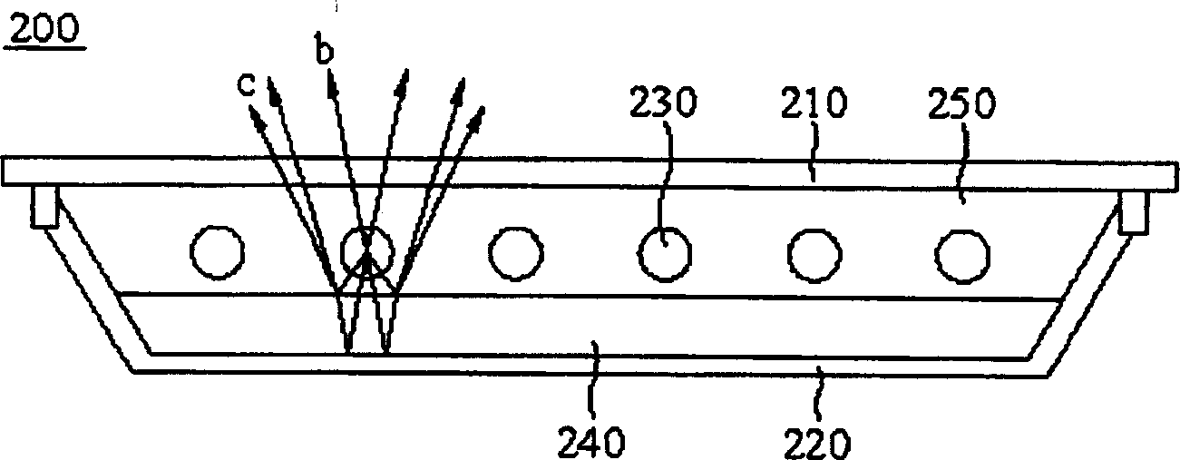
[0025] figure 2 It is a cross-sectional view of the direct-lit backlight assembly 200 according to the first embodiment of the present invention. A cavity 250 is formed by connecting a diffuser plate 210 and a reflector plate 220. A plurality of lamp tubes are arranged in the cavity 250 as light sources 230. Among them, one The light guide plate 240 is disposed between the light source 230 and the reflection plate 220 for changing the traveling route of the light.

[0026] After the light is emitted from the light source 230, the light b emitted from the upper part of the light source 230 directly passes through the diffusion plate 210 and exits the direct-lit backlight assembly 200; while the light c emitted from the lower part of the light source 230 first Entering the light guide plate 240, in the light guide plate 240, the optical path of the light c is changed, and then utilizes the reflection of the reflection plate 220, leaves the light guide plate 240, passes through ...

no. 2 example

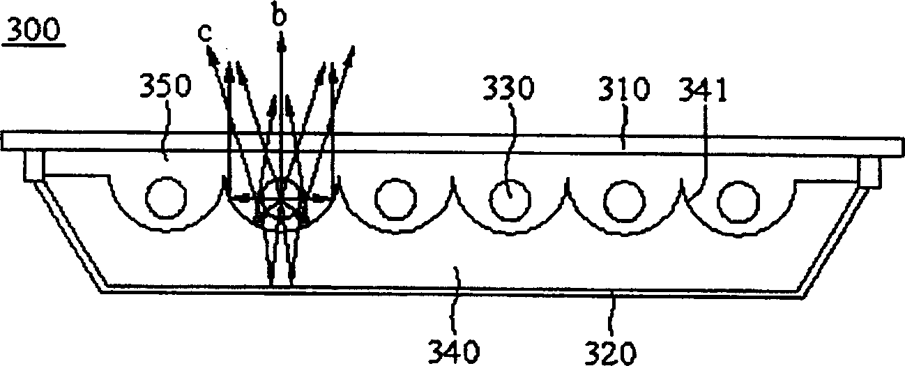
[0029] image 3 It is a cross-sectional view of a direct-lit backlight assembly 300 according to the second embodiment of the present invention. A cavity 350 is formed by connecting a diffuser plate 310 and a reflector plate 320. A plurality of lamp tubes are arranged in the cavity 350 as light sources 330. One of them The light guide plate 340 is arranged between the light source 330 and the reflector 320 to change the path of the light. The upper surface of the light guide plate 340 is designed as a mountain-shaped bulge between the light sources 330 according to the position of the light source 330. In an embodiment, the upper surface of the light guide plate 340 is in the form of a curved surface.

[0030] After the light is emitted from the light source 330, the light b emitted from the upper part of the light source 330 directly passes through the diffusion plate 310 and exits the direct-lit backlight assembly 300; while the light c emitted from the lower part of the lig...

no. 3 example

[0033] In this embodiment, in order to make the light more evenly distributed to achieve effective use, a diffuser 360 can be installed between the light guide plate 340 and the reflector 320 in the second embodiment as a light diffusion device, so that the light distribution is more efficient. uniform, such as Figure 4 As shown, light c is incident on the light guide plate 340 and then incident on the diffusion sheet 360. Due to the diffusion of the diffusion sheet 360, the light c is deviated. The direct type backlight assembly 300 is emitted through the diffusion plate 310 .


PUM


Abstract

The straight-down back light assembly includes one diffusion plate, one reflecting plate connected to the diffusion plate to form one cavity, one light source set inside the cavity, and one light guiding board set between the light source and the reflecting plate.

Description

technical field [0001] The present invention relates to a direct-type backlight assembly, in particular to a direct-type backlight assembly as follows: a light guide plate is arranged between a light source and a reflector to change the light path of the light emitted from the lower half of the light source to increase the optical efficiency . Background technique [0002] figure 1 It shows the structure diagram of the known direct type backlight assembly disclosed in Japanese Patent Publication Nos. 2001-059961 and 07-045114. In the known direct-type backlight assembly 100, a cavity 130 is formed by a back plate 110 and a diffuser plate 120, and a plurality of lamp tubes are arranged in the cavity 130 as light sources 140. , a reflective plate 150 is also provided; the reflective plate 150 is plated with silver, and the reflective plate 150 is stamped and bent to form a wave shape (or other various shapes) that facilitates light reflection, and then attached to the back p...

Claims


Application Information

Patent Timeline
Patent Type & Authority Applications(China)
IPC IPC(8): G02B5/02G02F1/13357
Inventor 章兴国黄允良邱欣柔游川倍李世达
Owner AU OPTRONICS CORP
Why Eureka
Try Eureka