Monitoring device composed of united video camera

A monitoring device and camera technology, applied in TV, color TV, image communication, etc., can solve problems such as inability to detect intruding objects, increase system scale, etc.

Active Publication Date: 2004-11-03
PANASONIC CORP
View PDF1 Cites 49 Cited by
  • Summary
  • Abstract
  • Description
  • Claims
  • Application Information

AI Technical Summary

Problems solved by technology

As shown in the figure, for example, if the wide-area imaging camera 1102 is installed on the ceiling 1101 and an intruding object is captured while looking down from the ceiling 1101, the area directly below the installation position of the wide-area imaging camera 1102 The area 1103 is not included in the imaging range 1104 of the wide-area imaging camera 1102, and becomes a blind spot, and intruding objects cannot be detected
Therefore, in order to detect intruding objects in the blind spot 1103, it is necessary to install another wide-area imaging camera, which increases the scale of the system.

Method used


Image

  • Monitoring device composed of united video camera
  • Monitoring device composed of united video camera
  • Monitoring device composed of united video camera

Examples


Embodiment approach 1

[0048] Figure 3 to Figure 11 It is a figure explaining 1st Embodiment of this invention. Explanation In this embodiment, the intrusion is tracked by using two rotating cameras whose supporting camera table can rotate in the left and right (pan) and up and down (tilt) directions, and which can change the field of view of the lens (zoom). Or, a method of enlarging the display on the screen.

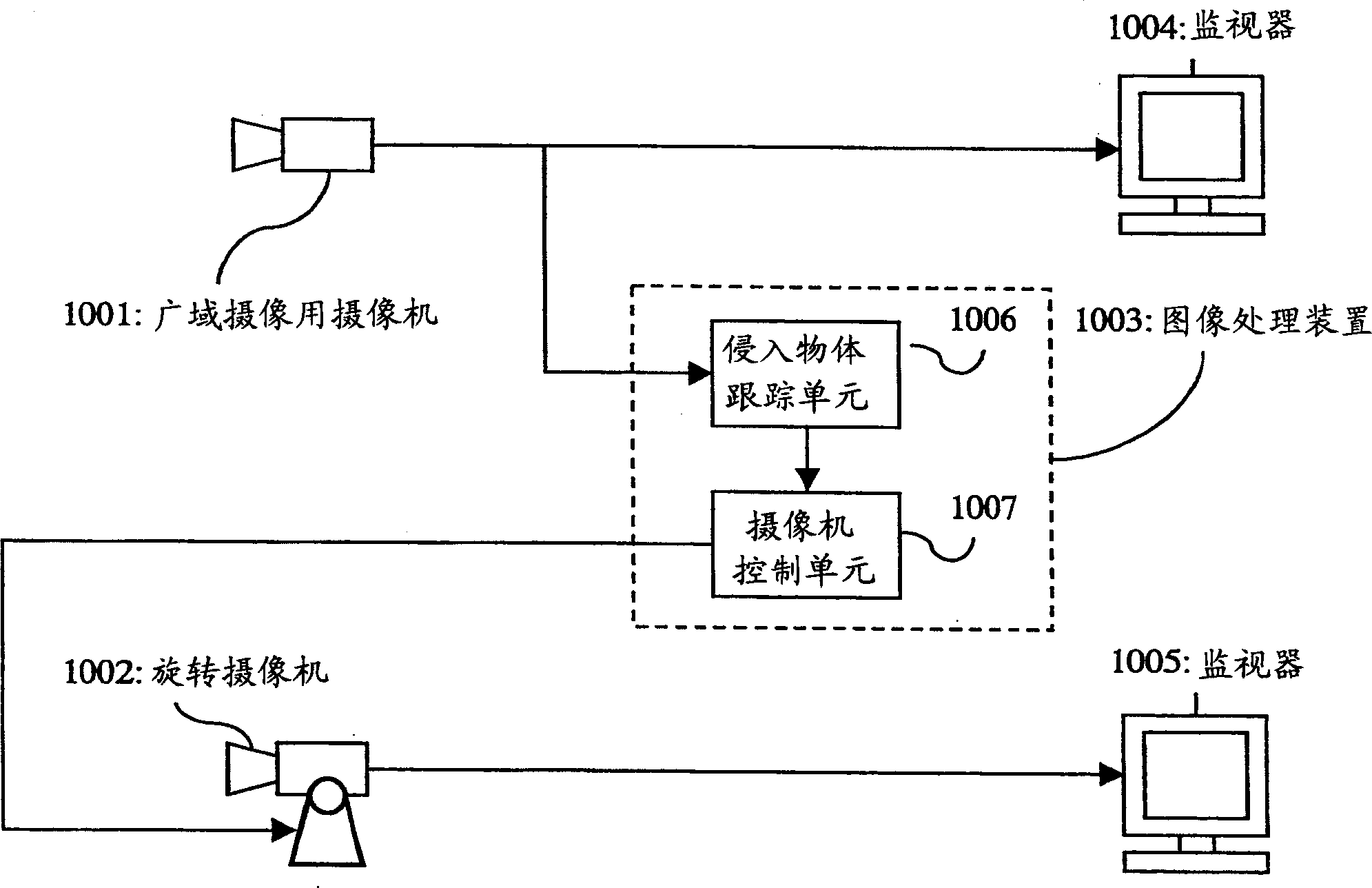
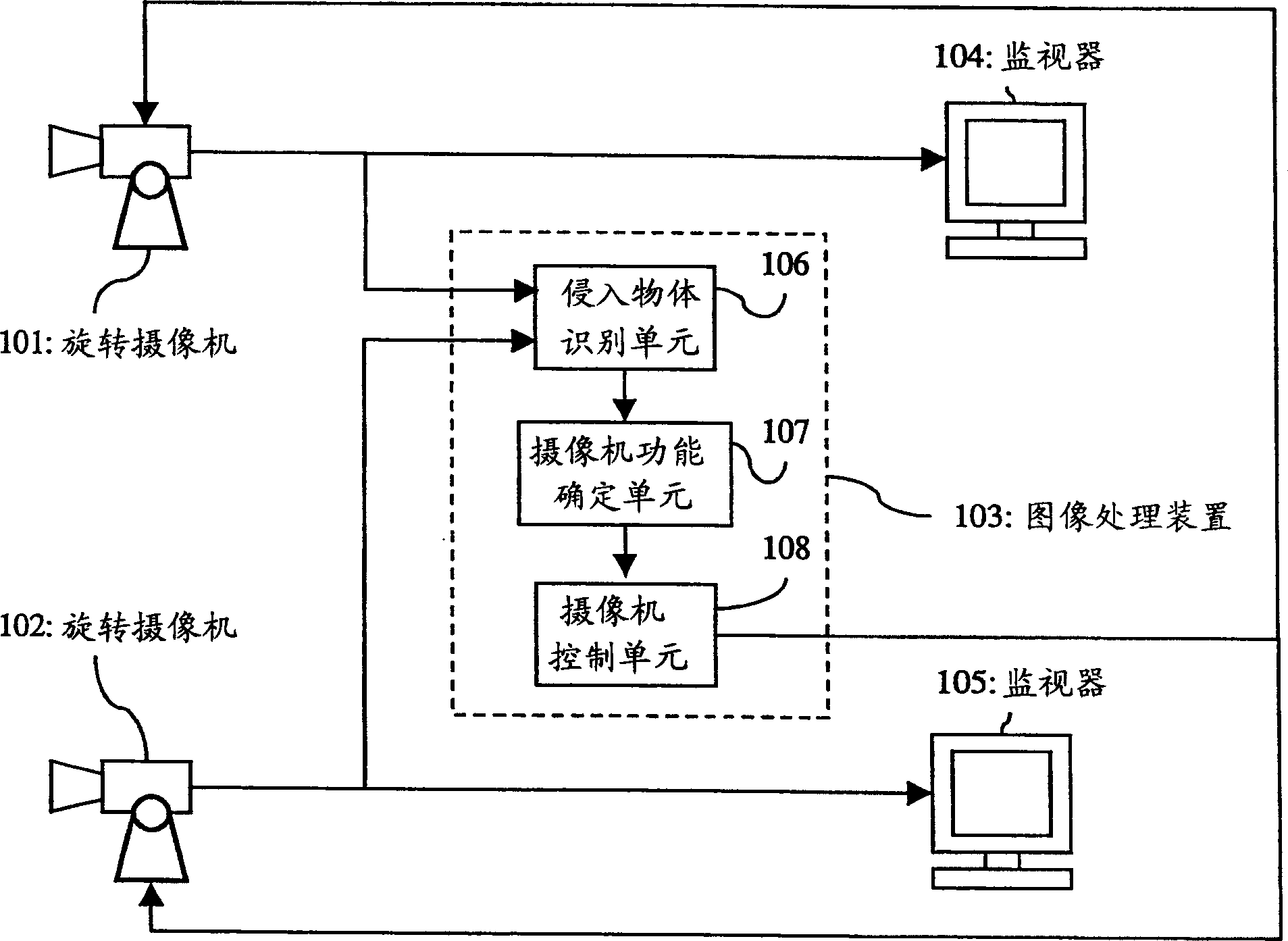
[0049] image 3 It is a block diagram showing the structure of the monitoring device of this embodiment. The monitoring device of the present embodiment is composed of the following parts: two rotating cameras 101, 102 that can be controlled by control signals for panning, tilting, and zooming; process the image signals sent from the rotating cameras 101, 102, and generate rotating cameras corresponding to the processing results An image processing device 103 for the control signal of 101, 102; and a monitor 104, 105 for displaying the image signal sent from the rotating camera 101, 102...

Embodiment approach 2

[0078] Figure 12 It is a block diagram showing the configuration of a monitoring device according to Embodiment 2 of the present invention. exist Figure 12 in, for with image 3 The same constituent elements are denoted by the same symbols, and their descriptions are omitted. The present embodiment is characterized in that the monitoring camera and its control function are combined with the face image recognition device as the image recognition unit, and the function of each rotating camera is assigned corresponding to the recognition result, thereby switching the camera function suitable for face image recognition. , which improves the face image recognition results.

[0079] exist Figure 12 Among them, 1201 is a face image recognition device for recognizing people's face images as an image recognition unit, which is composed of a face image recognition unit 1202 for selecting a specific face according to a face image, and a face image storage unit 1203 for storing fac...


PUM


Abstract

Provided is a monitoring apparatus in which an invading object is magnified and indicated without a dead space by the minimum number of cameras by making a plurality of cameras including a panning / tilting / zooming controllable rotary camera cooperate with each other. The monitoring apparatus comprises the plurality of cameras including the panning / tilting / zooming controllable rotary camera, an invading object recognizing means for processing an image signal from the rotary camera to trace a location of the invading object, a camera function determining means for assigning a tracing function to a first camera for which a predetermined direction of the monitoring target is settled within a photographic range in accordance with the situation of the monitoring target and assigning a wide area photographing function for photographing a monitoring space at a wide angle to a second camera, and a camera control means for controlling the plurality of cameras in accordance with the camera function means, and a camera to detect the monitoring target is switched in accordance with the direction of the monitoring target, so that the invading object is traced without dead angle by the minimum number of cameras.

Description

technical field [0001] The invention relates to a monitoring device which uses a plurality of monitoring cameras and an image processing device to automatically detect intruding objects and enlarge and display them on a screen. Background technique [0002] In recent years, in the field of surveillance, there have been not only systems that display image signals transmitted from cameras on the screen, but also systems that use image processing devices to analyze the signals, determine the location of abnormalities, and prompt other monitors. nearby systems. [0003] As an example of such prior art, there is an example shown in Japanese Unexamined Patent Application Publication No. 11-69342 (Japanese Patent Laid-Open No. 69342 / 1999). This patent document discloses the following system: In order to detect intruders, a camera with a lens having a wide field of view is used, and a rotating camera capable of panning (left and right), pitching (up and do...

Claims


Application Information

Patent Timeline
Patent Type & Authority Applications(China)
IPC IPC(8): H04N7/18
CPCG08B13/19608G08B13/1963G08B13/19628G08B13/19695G08B13/19641H04N7/181
Inventor 石上智英丸谷健介冈田晋
Owner PANASONIC CORP
Why Eureka
Try Eureka