A method for acquiring a high-frequency image sequence and a time-sharing and spectroscopic device adopted therefor

A time-sharing light-splitting and optical-axis technology, applied in the field of light-splitting technology, can solve the problems that the incident light cannot be distributed to the back-end detector, can only be used at a reduced frequency, and the luminous flux is reduced, so as to improve the identification ability and measurement accuracy, and save costs. , the effect of increasing parallelism

Active Publication Date: 2014-10-15
XI'AN INST OF OPTICS & FINE MECHANICS - CHINESE ACAD OF SCI
View PDF6 Cites 0 Cited by
  • Summary
  • Abstract
  • Description
  • Claims
  • Application Information

AI Technical Summary

Problems solved by technology

If the project requires an integration time of 1ms, it can only be used at reduced frequency at this time, and the highest can only be used less than 250Hz
The optical efficiency of this kind of catadioptric system cannot be 100%. The further you go to the back end of the system, the more obvious the decrease in luminous flux is.
In addition, this kind of system can only selectively use a certain fixed wavelength band, and cannot distribute all the incident light to the back-end detector. Therefore, when the wavelength band of interest changes, it is necessary to replace the front-end optical system in addition to the detector. Poor adaptability and high cost

Method used


Image

  • A method for acquiring a high-frequency image sequence and a time-sharing and spectroscopic device adopted therefor
  • A method for acquiring a high-frequency image sequence and a time-sharing and spectroscopic device adopted therefor
  • A method for acquiring a high-frequency image sequence and a time-sharing and spectroscopic device adopted therefor

Examples


Embodiment Construction

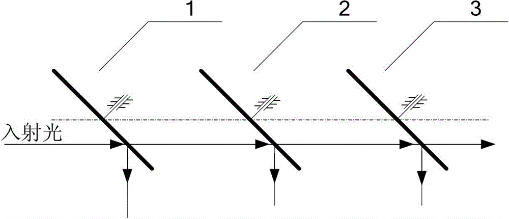
[0026] The present invention uses a plurality of rotating impeller mirror groups, through the through holes or reflectors regularly arranged on the impeller, time-splitting the incident light to different detectors for synchronous exposure, and then the subsequent acquisition circuit detects each The output of the detector is collected and synthesized, and finally a high-frequency (multiplied) infrared image sequence is generated.

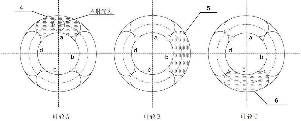
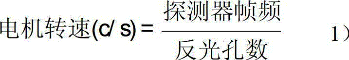
[0027] The number of reflectors on the first impeller determines the system speed, and increasing the number of reflectors can effectively reduce the speed of the impeller. The corresponding relationship between the motor speed, the number of reflective holes and the frame frequency of a single detector is:

[0028]

[0029] The number of light-transmitting holes on each impeller should be greater than or equal to the number of light-reflecting holes. When there are multiple reflectors on the impeller, the reflectors and the through holes must ...


PUM


Abstract

The invention provides a method for acquiring a high-frequency image sequence and a time-sharing light splitting device adopted by the method for acquiring the high-frequency image sequence. A plurality of rotary impellers are arranged, the rotary planes of the rotary impellers are parallel to each other, and rotary centers are positioned on a same line; N plus M hole positions are circumferentially distributed on each rotary impeller, the centers of all the hole positions are positioned on a same circle by taking the rotary centers of the impellers as centers, wherein the M hole positions are through holes, reflecting mirrors are arranged on the N hole positions, and N is not less than M; and an optical axis of input light is parallel to the line of the rotary centers, and the included angle of the optical axis of the input light and the reflecting surface of the reflecting mirror can ensure that the reflecting light cannot shield emergence. The method and the device can be used for the recording and measuring systems of large area-array cameras or high-sensitivity cameras, a time-sharing light splitting technology is adopted to enable another camera to expose when one camera reads the data, so that the parallelism of a measuring system is increased, the integral measurement frame frequency of the system is increased, and the measurement of high-speed variation processes or objects which do high-speed relative motion is benefited.

Description

technical field [0001] The invention relates to a light splitting technology, in particular to a technology for time-divisionally distributing incident light to different light paths. Background technique [0002] For photoelectric imaging detectors, especially infrared detectors, due to the limitation of semiconductor technology level, the charge transfer time during readout is too long, so the measurement frame rate of the detector is usually low and it is difficult to effectively improve it. Taking the 320×256 HgCdTe mid-wave infrared focal plane detector as an example, if the data readout speed of the area array is 6.6MHz per channel, and 4 channels are read in parallel, the corresponding readout time is 320×256 / 4 / 6600000 = 0.0031s. The maximum frame rate of the focal plane array can be 320Hz, and the integration time at this time is only (1 / 320-0.0031)×10 -6 s=22us. If the project requires an integration time of 1ms, it can only be used at reduced frequency at this t...

Claims


Application Information

Patent Timeline
Patent Type & Authority Patents(China)
IPC IPC(8): G01J5/02G01J5/08G01C11/02G02B26/04
Inventor 韩俊锋高昕江波唐嘉周泗忠段晶
Owner XI'AN INST OF OPTICS & FINE MECHANICS - CHINESE ACAD OF SCI
Why Eureka
Try Eureka