Magnetic suspension rail inspection vehicle chassis with guide wheel system

A technology of maglev track and guide wheel, which is applied in the direction of railway inspection vehicles, etc., can solve the problems of the distance change of the guide rail guide surface, the inability to guide the maglev track beam, and the limitation of application range, so as to achieve the effect of preventing slipping

Inactive Publication Date: 2004-11-10
TONGJI UNIV +1
View PDF1 Cites 25 Cited by
  • Summary
  • Abstract
  • Description
  • Claims
  • Application Information

AI Technical Summary

Problems solved by technology

"Although the driving wheel of this utility model is located on the top of the monorail, and guide wheels are respectively installed on both sides of the lower part, the distance between the rims of the guide wheels on both sides is just equal to the width of the monorail, so it can be guided along the monorail, but its The running part cannot solve the problem of the wheel speed difference between the inner and outer wheels when driving along a wide single-track curved road, and the problem of the distance change of the guide rail guide surface between several pairs of guide wheels on both sides. The wheel rim is very narrow, and the system structure is still only suitable for guided driving on a narrow track, and cannot be guided at a high speed on the maglev track beam of a maglev high-speed train. Therefore, the application range of this type of technology is greatly restricted. limit

Method used


Image

  • Magnetic suspension rail inspection vehicle chassis with guide wheel system
  • Magnetic suspension rail inspection vehicle chassis with guide wheel system
  • Magnetic suspension rail inspection vehicle chassis with guide wheel system

Examples


Embodiment Construction

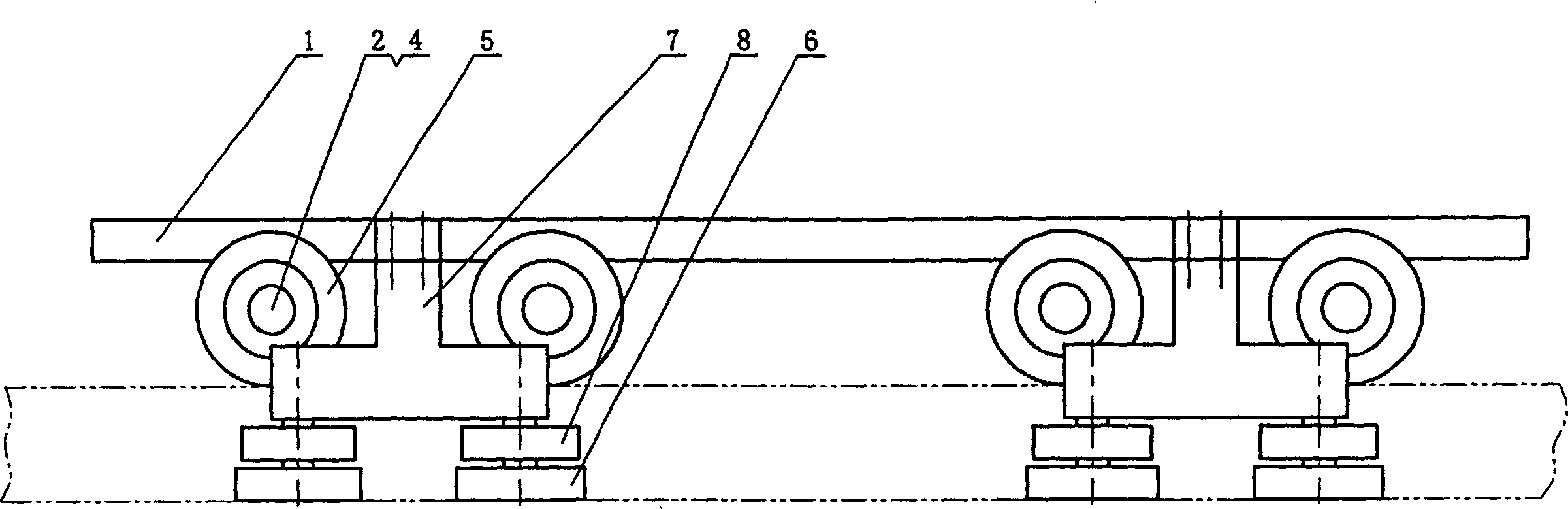
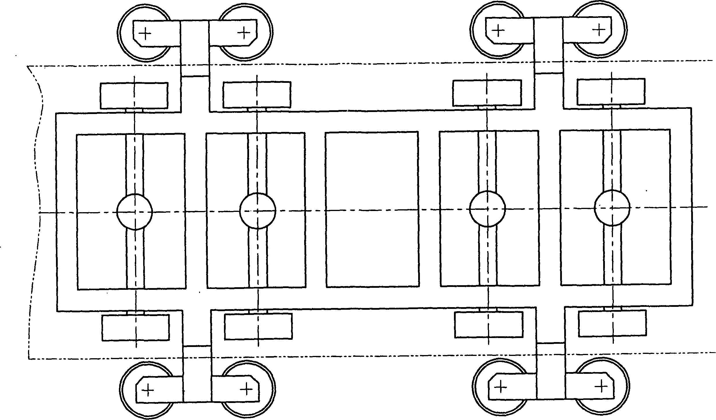
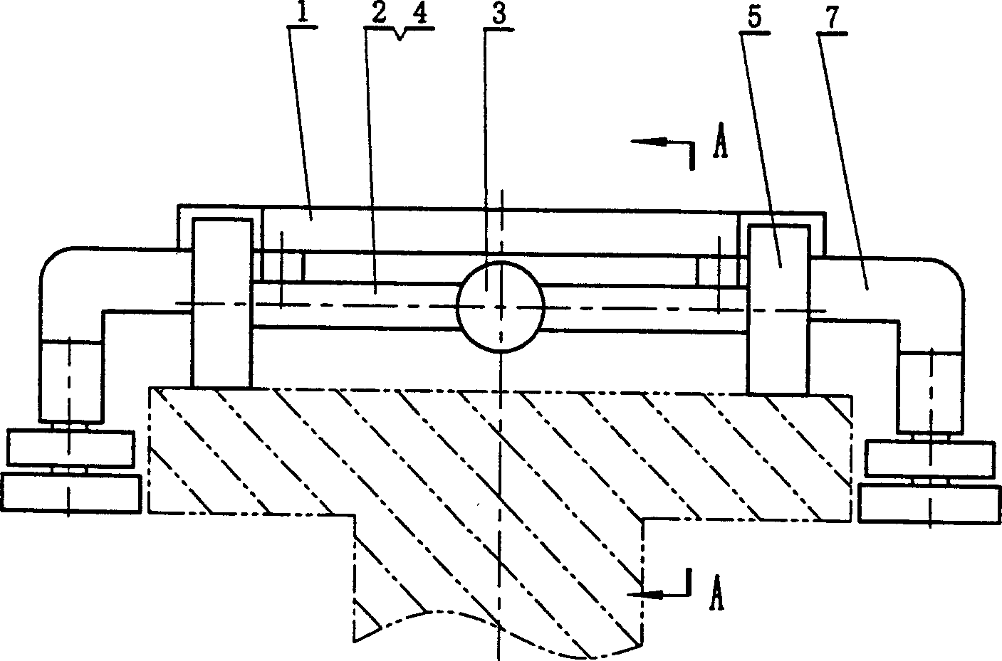
[0013] Such as figure 1, figure 2, Figure 3 and Figure 4 Shown, the present invention comprises: undercarriage 1, vehicle driving axle 2, gear differential 3, axle shaft 4, rubber tire wheel 5, rubber tire guide wheel 6, guide wheel frame 7, and its connection mode is: several without The vehicle drive axle 2 with the steering function is fixed on the undercarriage 1 in parallel, the middle part of the vehicle drive axle 2 is provided with a gear differential 3, and the two ends of the gear differential 3 are respectively connected to the half shaft 4, and the rubber tire wheels 5 Be arranged on the half shafts 4 of the two output ends of each vehicle drive axle 2, the rubber tire guide wheels 6 are arranged on the wheel shafts at the two ends of the guide wheel frame 7 and can rotate freely, the axis of the rubber tire guide wheels 6 and the axis of the rubber tire wheels 5 Vertical, the rim wheel surface of the rubber tire guide wheel 6 faces the upper side of the mag...


PUM


Abstract

The invention is a chassis of magnetic suspension test vehicle with guide wheel system, including: underframe, vehicle driving bridge, gear differential, semishaft, rubber tyre wheel, rubber tyre guide wheels, and guide wheel frame. There are several vehicle bridges parallelly fixed on the underframe, and the middle and inside of the underframe are set with the gear differential and the semishaft, respectively, and the rubber tyre wheel are set at tow ends of the underframe, the rubber tyer guide wheels are set on the wheel shafts at two ends of the guide wheel frame and can freely rotate, many groups of guide wheel frames are allocated vertically and symmetrically along the underframe and fixed at the bottom of the two opposite sides of the underframe, the axis of the rubber tyre guide wheel is vertical to that of the rubber tyre wheel, the distance between the flanges of the corresponding guide wheels on two side of the underframe is greater than the width of the guide surface of the guide rail, and thus the flanges provide side location support and guide for the test vehicle safely running on the magnetic suspension railway beams along the railway. It has reasonable structure, smooth running and good guiding performance, and low running noise.

Description

technical field [0001] The invention relates to a chassis of a maglev rail inspection vehicle, in particular to a chassis of a maglev rail inspection vehicle with a guide wheel system. It belongs to the field of rail transit engineering. Background technique [0002] The railway vehicle chassis that is used for rail traffic at present, its walking part is driven by several railway moving wheel axles that axle gear boxes and wheelsets are housed, or known railway vehicle bogies, but all are only applicable to railway rail running, its A steel wheel suitable for the cross section of the rail is adopted and supported and guided by the shoulder of the wheel rim and the rail. Other forms of walking, supporting, and guiding systems, such as the wheel structure for rail-mounted cranes, loaders or roadway stackers, are also basically the same as the wheel structure of railway vehicles. The structure of the sleeper system of the maglev high-speed train is completely different from ...

Claims


Application Information

Patent Timeline
Patent Type & Authority Applications(China)
IPC IPC(8): B61D15/12
Inventor 张建武何维廉顾力强包继华黄宏成
Owner TONGJI UNIV
Why Eureka
Try Eureka