Thread-clamping and thread-loosing apparatus for straight-bar machines

A technique for thread pressing and thread removal, applied in textile and papermaking, weft knitting, knitting, etc., can solve the problems of affecting the opening and unhooking of the latch, cumbersome replacement of sinkers, inconvenient installation and disassembly, etc., and achieves quality reliability. The effect of improving, good weaving quality and quick installation and disassembly

Inactive Publication Date: 2004-11-10
冯加林
View PDF0 Cites 5 Cited by
  • Summary
  • Abstract
  • Description
  • Claims
  • Application Information

AI Technical Summary

Problems solved by technology

The sinker is set on the non-reed side of the knitting needle and is close to the knitting needle. When knitting, especially when weaving changes the structure, due to the oblique pull effect of the coil, the needle latch will be biased in the direction of the oblique pull when it is opened. If the latch is biased toward the sinker, it will collide with the sinker and affect the opening and stripping of the latch, resulting in a hole
[0003] Existing sinker replacement is extremely cumbersome
Because generally the sinker and the ring stripper are provided with a positioning hole, hundreds of pairs of the sinker and the stripper are installed on the steel wire rotating shaft at intervals through the positioning hole, and the sinker often needs to be replaced due to wear and deformation. But every time a sinker needs to be replaced, the steel wire rotating shaft must be pulled out, and a new one must be put on again after replacing a sinker. The installation and disassembly are very inconvenient, time-consuming and costly.

Method used


Image

  • Thread-clamping and thread-loosing apparatus for straight-bar machines
  • Thread-clamping and thread-loosing apparatus for straight-bar machines
  • Thread-clamping and thread-loosing apparatus for straight-bar machines

Examples


Embodiment Construction

[0017] The present invention and its advantages will be further described below in conjunction with the accompanying drawings.

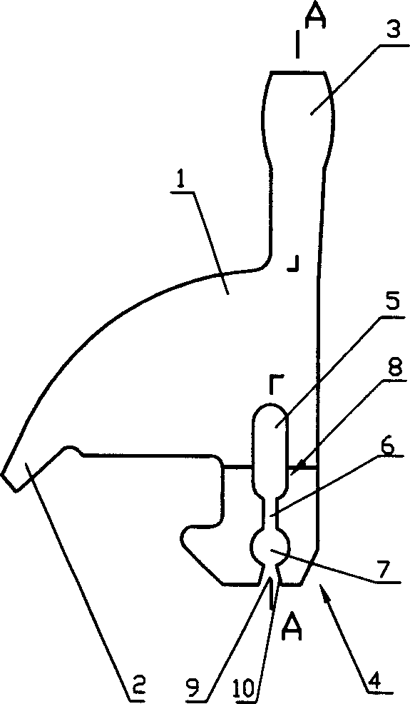
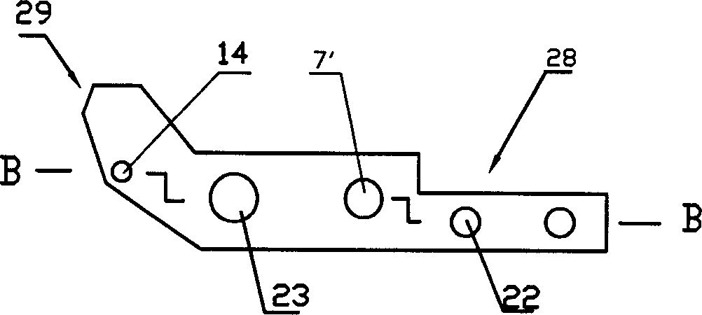
[0018] figure 1 , figure 2 It is the sinker device designed in this embodiment. It is stamped by 0.6mm 65Mn steel strip. After heat treatment, the surface hardness is HRC 52-58. There is a half-arched plane base 1, and its contraction end extends out to the lower side. A crimping part 2 is provided, and a needle bell part 3 extends from the upper side of the high end of the arch, and the lower side of the high end of the arch extends toward the left side of the base 1 through two consecutive bends at 90° angles to extend downwards to a mounting part 4 , the mounting part 4 is parallel to the base part 1 and the crimping part 2, and the distance between the two planes is 0.45 mm. A positioning hole 7 is provided on the mounting part 4 with a diameter of φ195-0.05 mm. The upper end of the positioning hole 7 is provided with a The long slotted hole 8...


PUM


Abstract

The invention relates to a line-pressing and-stripping device for flat knitting machine, and its technical project: it includes depositing piece, de-circle piece, inserted piece, needle plate groove and steel wire rotating shaft, where the depositing piece and the de-circle piece are connected with the rotating shaft, the bottom of the de-circle piece is inserted in the needle groove and one side of the de-circle piece is tightly set with the inserted piece, the bottom end of the depositing piece extends downwards a plane parallel with the original plane in the direction of one side surface at two continuous basic 90 deg. bending angles; the top of the locating hole is set with a long groove hole and there is a gap on the edge of the bottom end of the locating hole and the locating hole connects the long groove hole and the gap, the depositing piece is connected with the rotating shaft in socketing mode; one side surface of the de-circle piece is set with several bosses. Its advantages: (1) good weaving quality and the reliability is largely enhanced; (2) accurate locating, largely saving time and labour and the product cost is reduced; (3) simple and easy to make and low cost.

Description

technical field [0001] The invention relates to a knitting flat knitting machine, and more specifically relates to a thread pressing and stripping device for a flat knitting machine. Background technique [0002] At present, in the knitting flat knitting machine, the sinker and the stripping piece are all installed on the steel wire rotating shaft in a piercing mode so as to be positioned on the needle plate. Wherein the sinker can rotate around the rotating shaft within a certain angle range, and the stripping piece is fixed, and its lower end is embedded in the needle plate groove together with the closely placed side by side inserts. The sinker is set on the non-reed side of the knitting needle and is close to the knitting needle. When knitting, especially when weaving changes the structure, due to the oblique pull effect of the coil, the needle latch will be biased in the direction of the oblique pull when it is opened. If the latch is biased toward the sinker, it will ...

Claims


Application Information

Patent Timeline
Patent Type & Authority Applications(China)
IPC IPC(8): D04B15/06
Inventor 冯加林巫友群
Owner 冯加林
Why Eureka
Try Eureka